CNC from Screenprinter - Part 2
CNC ·Conversion of the machine’s base
This part of the series is about converting the old screenprinter’s base in something that can be used for CNC machining. For the previous part, see here.
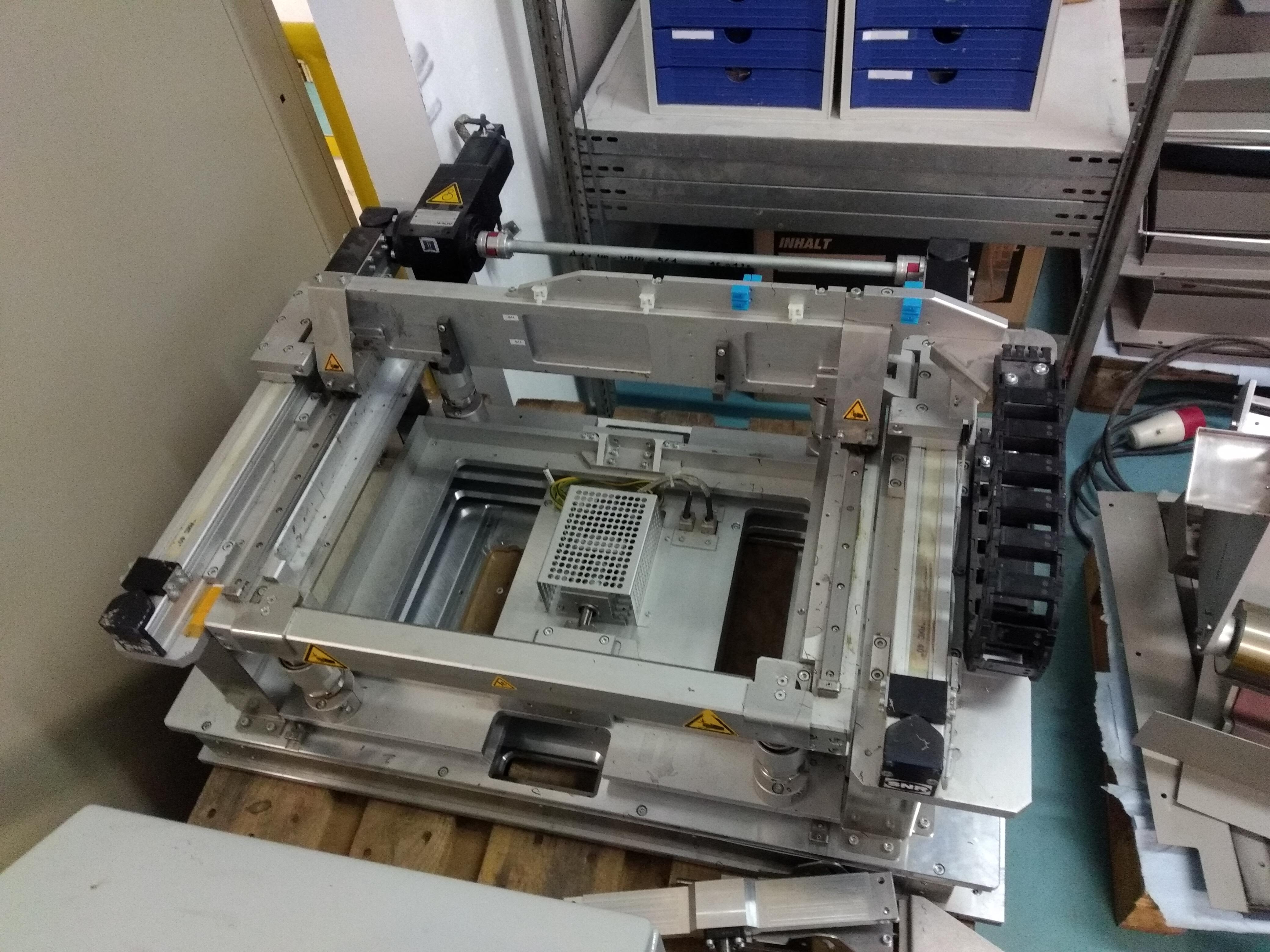
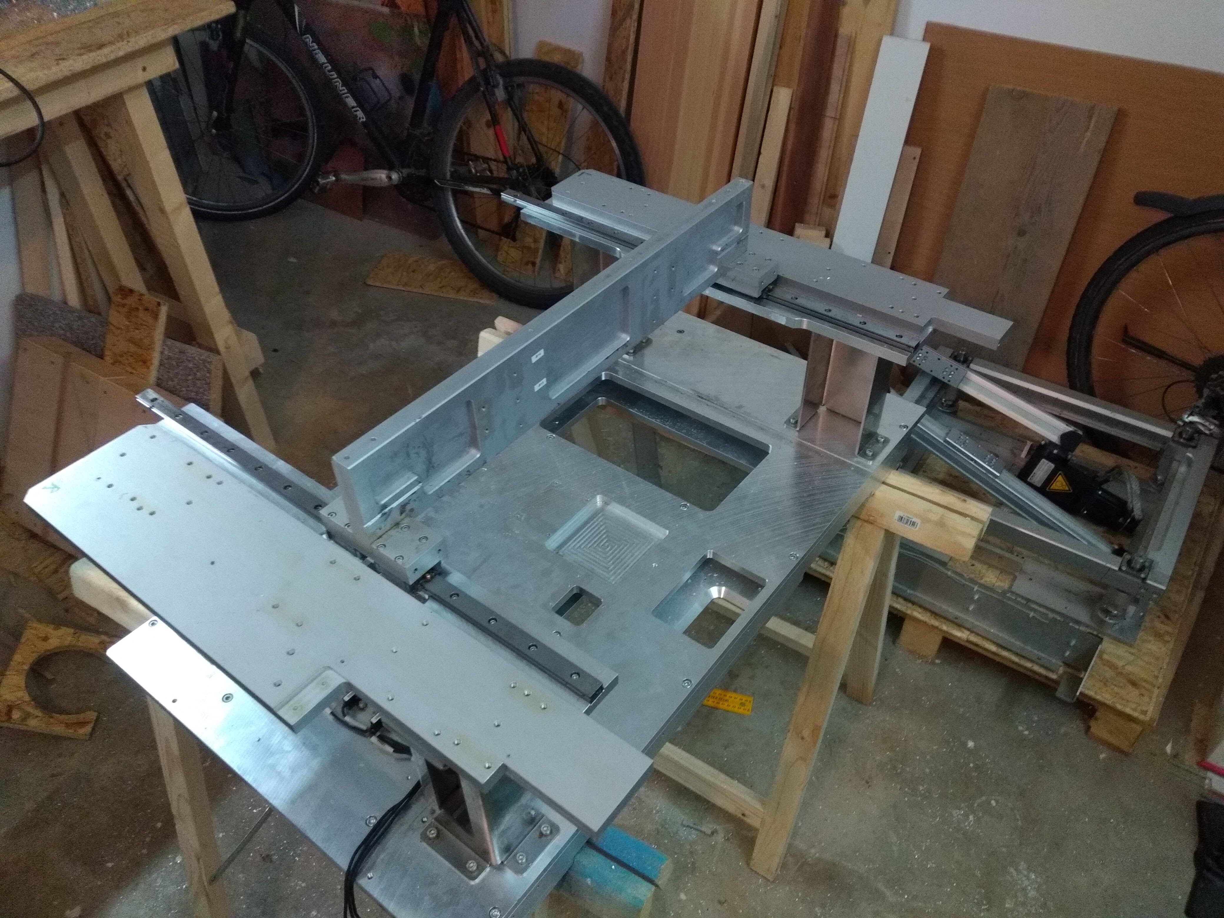
As you can kind-of see from the above picture, the original machine’s y-axis rails are mounted on an inner frame which slides up and down. This mechanism is not useful as it obstructs the working volume and only introduces more play in the whole setup. Instead, the rails should really be mounted to the side posts directly. But as I do not have access to a big milling machine to create fancy parts, we need a solution that does not involve extensive machining operations.
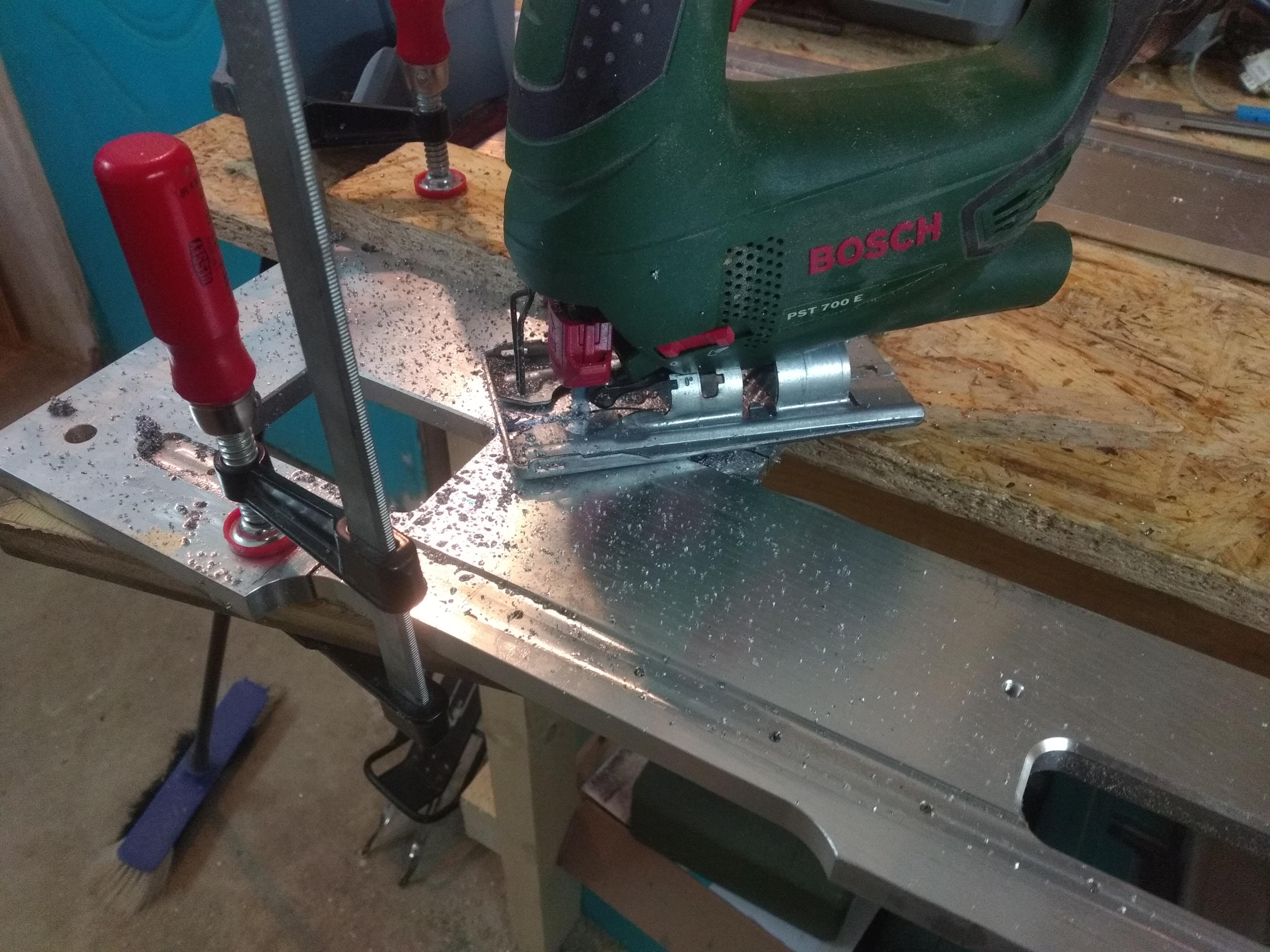
From one 12mm thick baseplate that we got with the screenprinter, two pieces are cut using a jigsaw. This works surprisingly well if you are patient enough. Those plates already had slots and threads to accept the 16mm linear rails and were almost of the perfect size. Only non-functional edges had to be cut with the jigsaw, a lucky incidence.
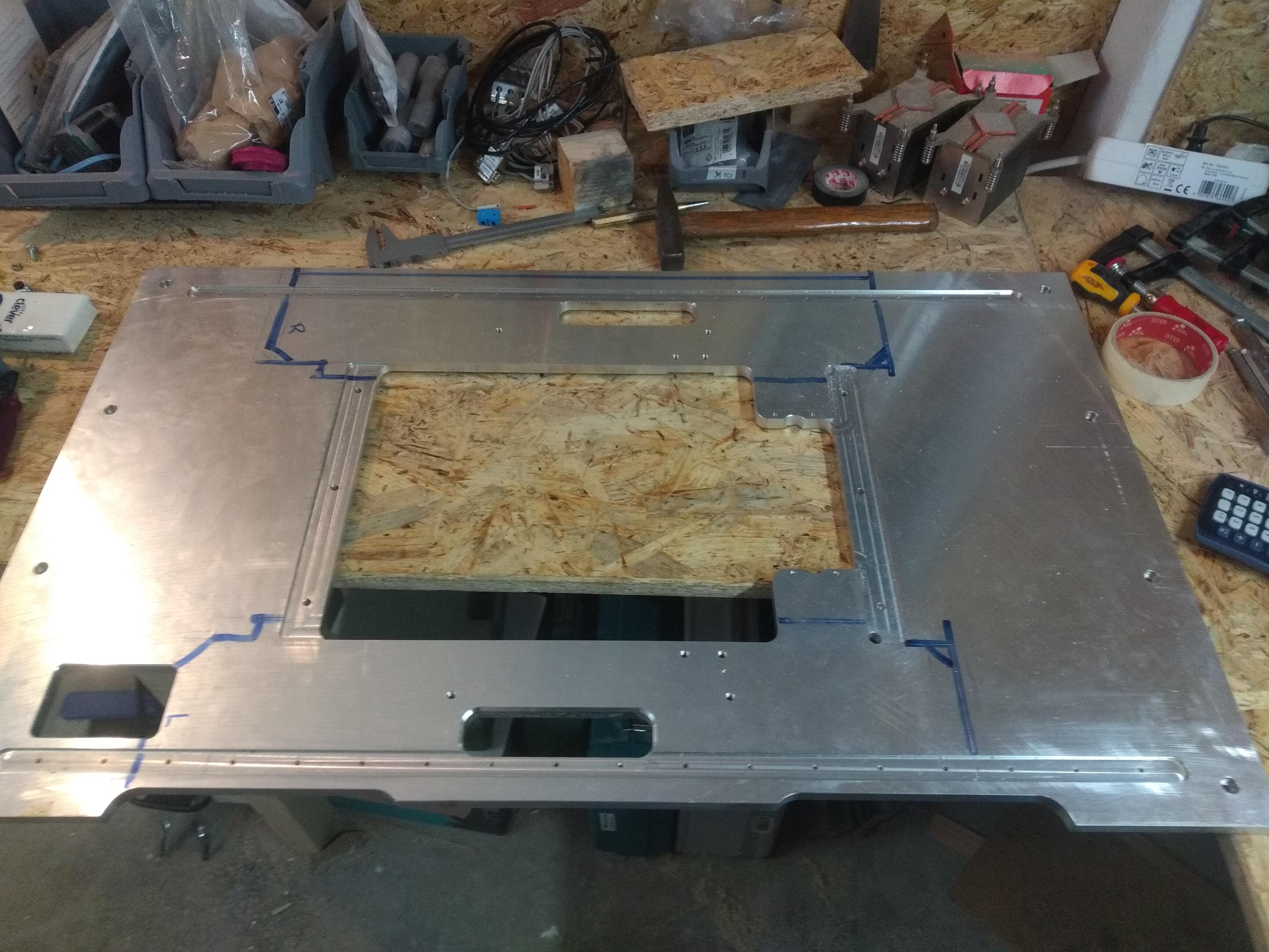
The hole locations from the machine frame are transferred and drilled oversized, so that the horizontal alignment can be tweaked when the machine is assembled.
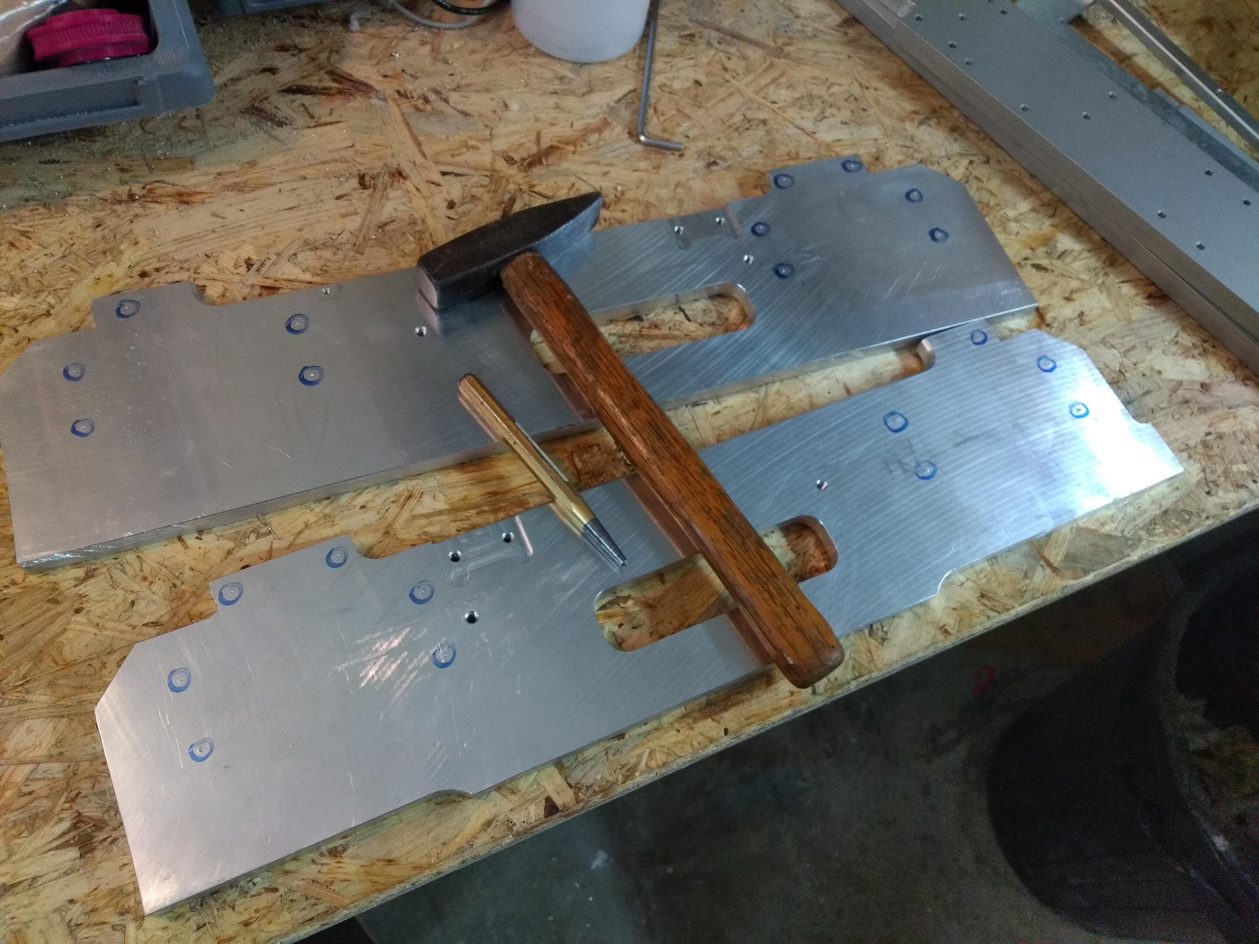
The pieces are sandwiched between the original aluminium plate and the posts. Now I know that mounting linear rails on an overhanging aluminium plate is not really considered the proper way by mechanical engineers, but this was the solution for me to get this done accurately with the available materials and without a big milling machine. Considering that the plates are 12mm thick and the overhang is effectively only about 25mm, it should not be so bad, I think.
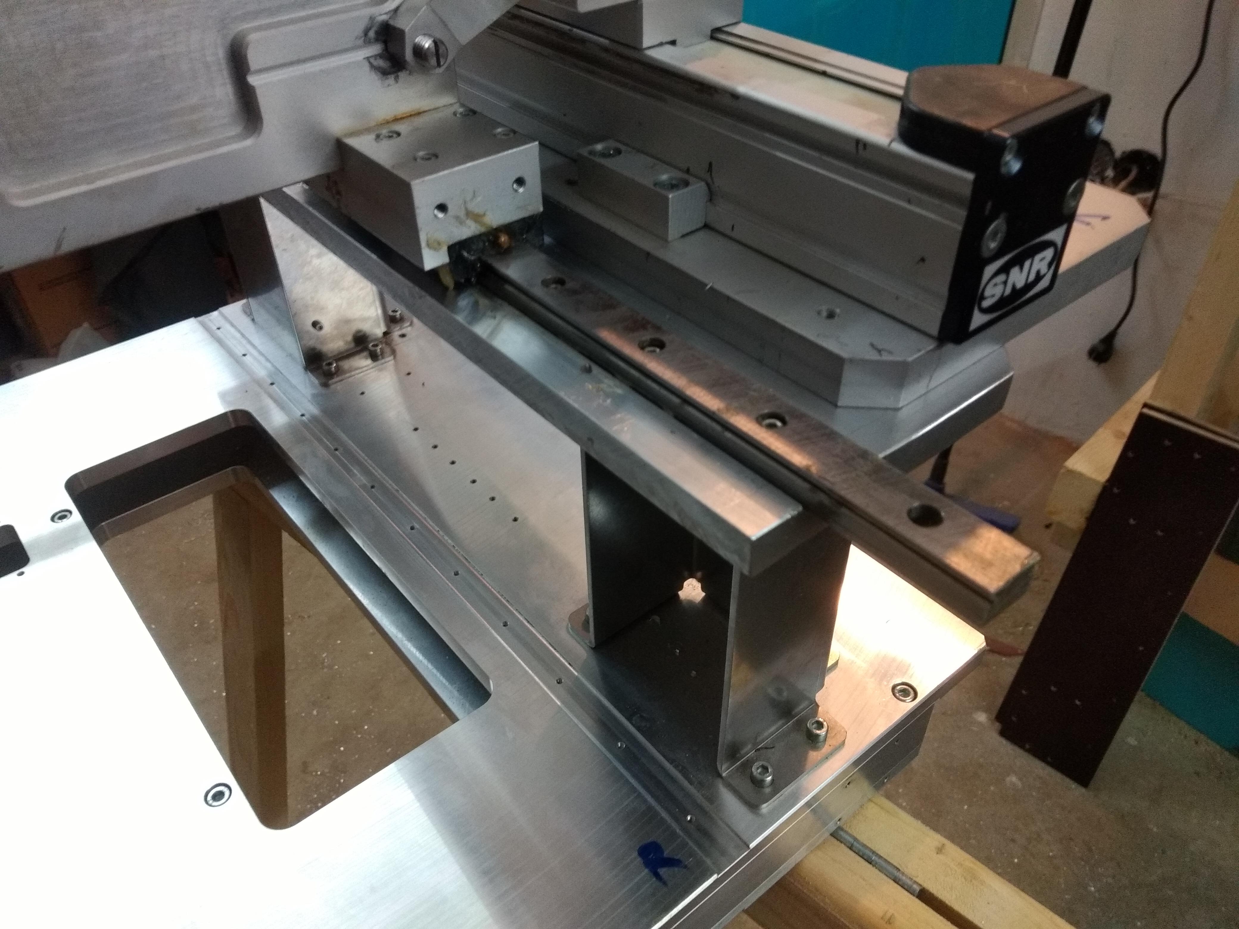
Of course, there is no possibility to tweak the alignment of the rails in the vertical direction except from shimming maybe, as the thicknesses of the plates basically dictate where they end up. My main concerns with this approach was that it would jam and you would not be able to get rid of it. But as it turned out, the parts from the original machine were very accurate, and the base also allows for some minor flex, so the bridge now runs nice and smooth. You hardly notice any difference in resistance along its travel range at all.
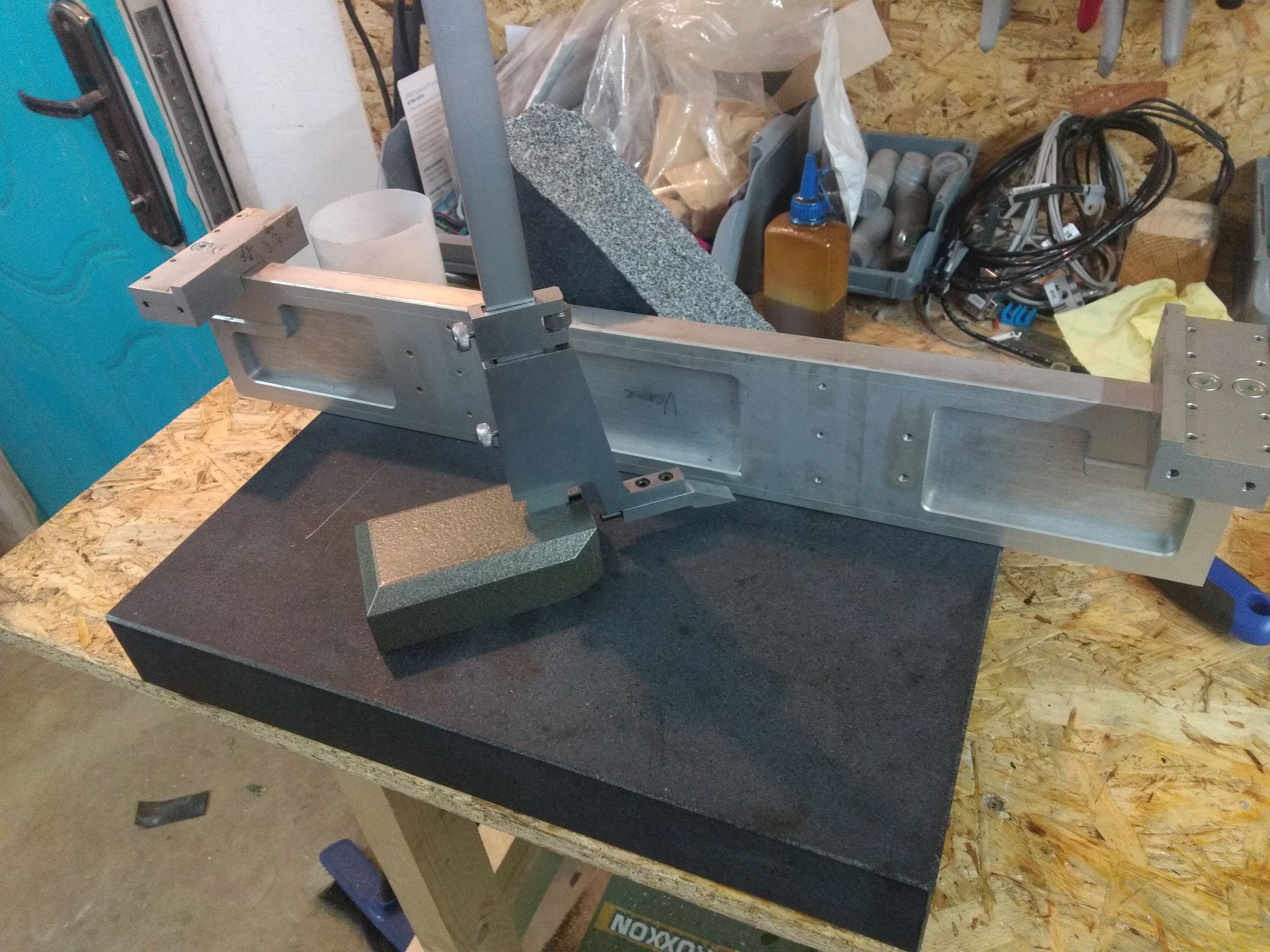
Next, the rails of the x-axis have to be mounted. Previously, the machine had no x-axis, so we need to start from scratch here. Luckily the original bridge is machined very accurately, so its really just a matter of laying out hole positions and cutting the threads.
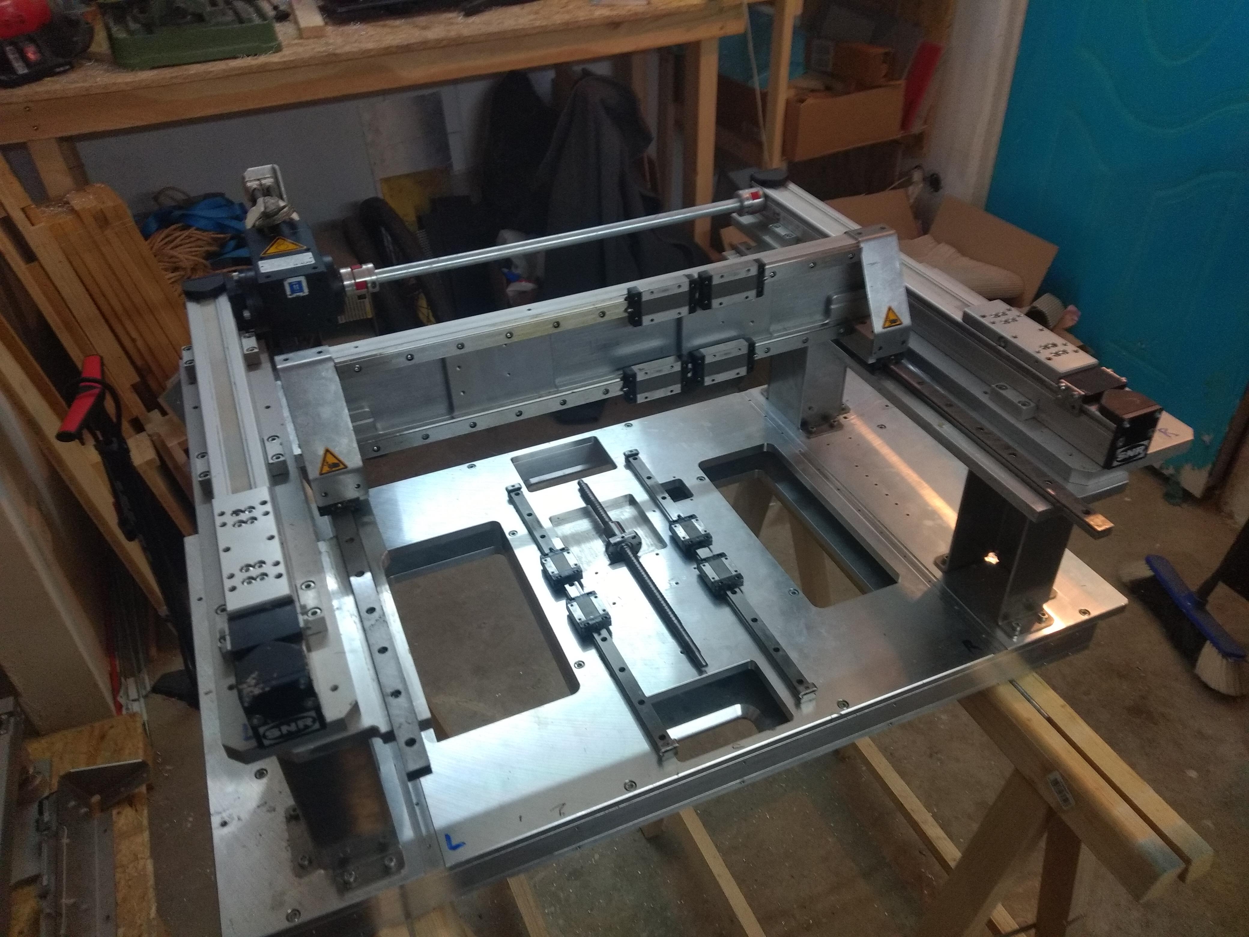
With the rails for the x-axis, also scavenged from the old screenprinter, the construction already looks like the base of a CNC-machine.
In the next part, the z-axis will be built.