CNC from Screenprinter - Part 3
CNC ·Building a z-axis
This part of the series is about building a z-axis for the machine from scratch, but using the materials from the old screenprinter. For the previous part, see here. I really want to thank two friends of mine from university at this point for helping me out with all the cutting and drilling necessary.
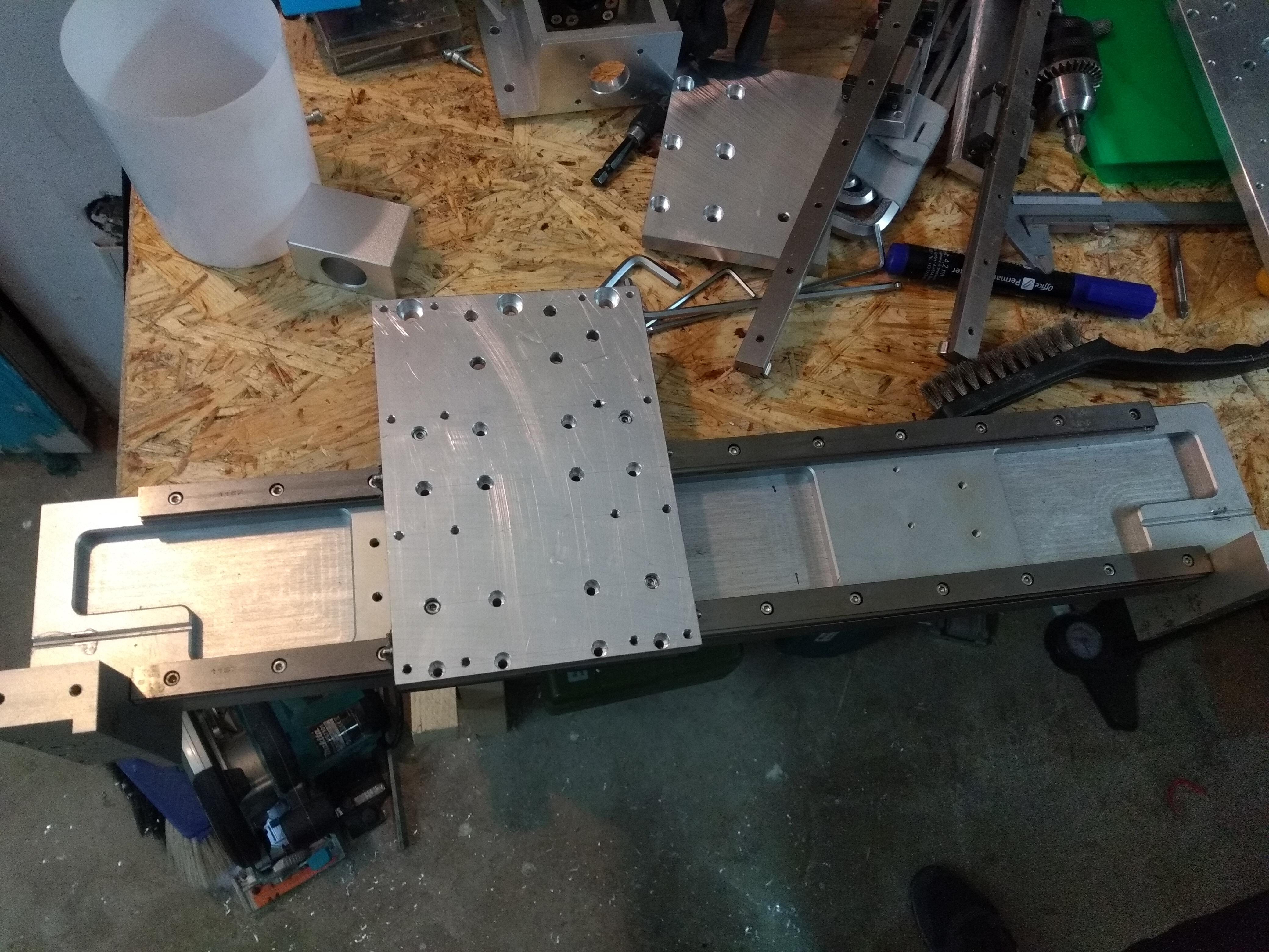
The original machine had no z-axis as such. The rubber ledge to smear the paint through the screen was pushed down by a pneumatic cylinder with very little stroke. So it has to be built completely from scratch. Basically, some of the existing 16mm linear rails in combination with a 1204 chinese ballscrew from ebay should do, I concluded. But as this assembly was quite complicated, some plans were drawn first on paper.
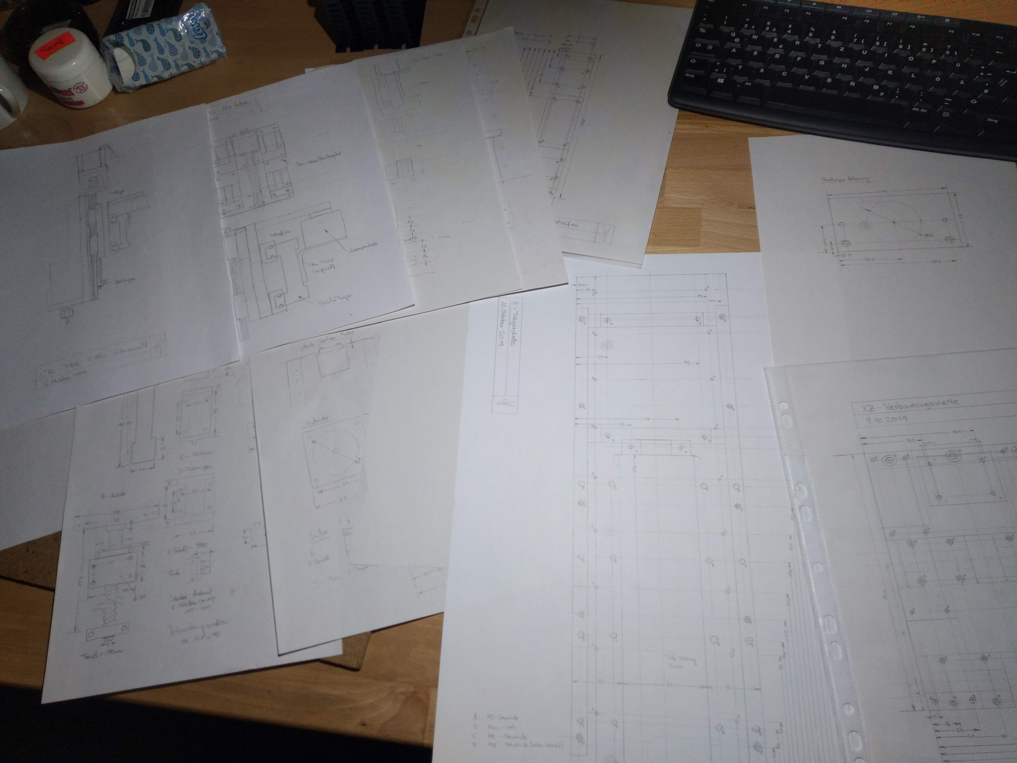
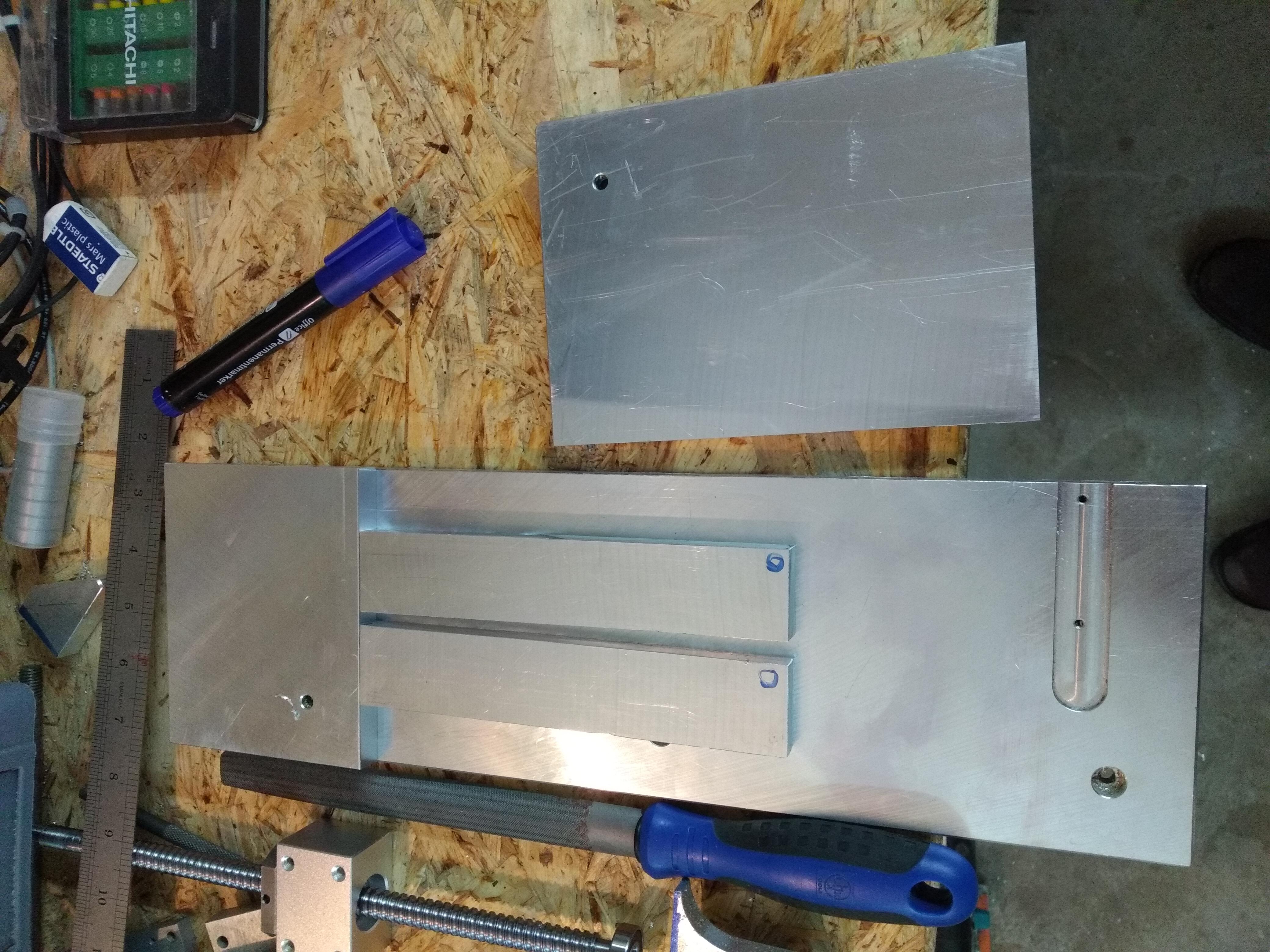
From other material left over from the screenprinter’s baseplate, the necessary pieces for the z-axis are cut out using an old blade on my small homemade table saw. This went fast and also remarkingly precise. The parts were only a few tenths of a millimeter off the desired dimension. We would never have been able to cut them that straight and fast with a jigsaw. A word of caution, however: This is not the intended way to use a table saw, so you really need to know and think what you are doing. You must never stand behind the blade but always beside, never come too close to the blade with your hands but use push sticks, and always wear safety glasses!
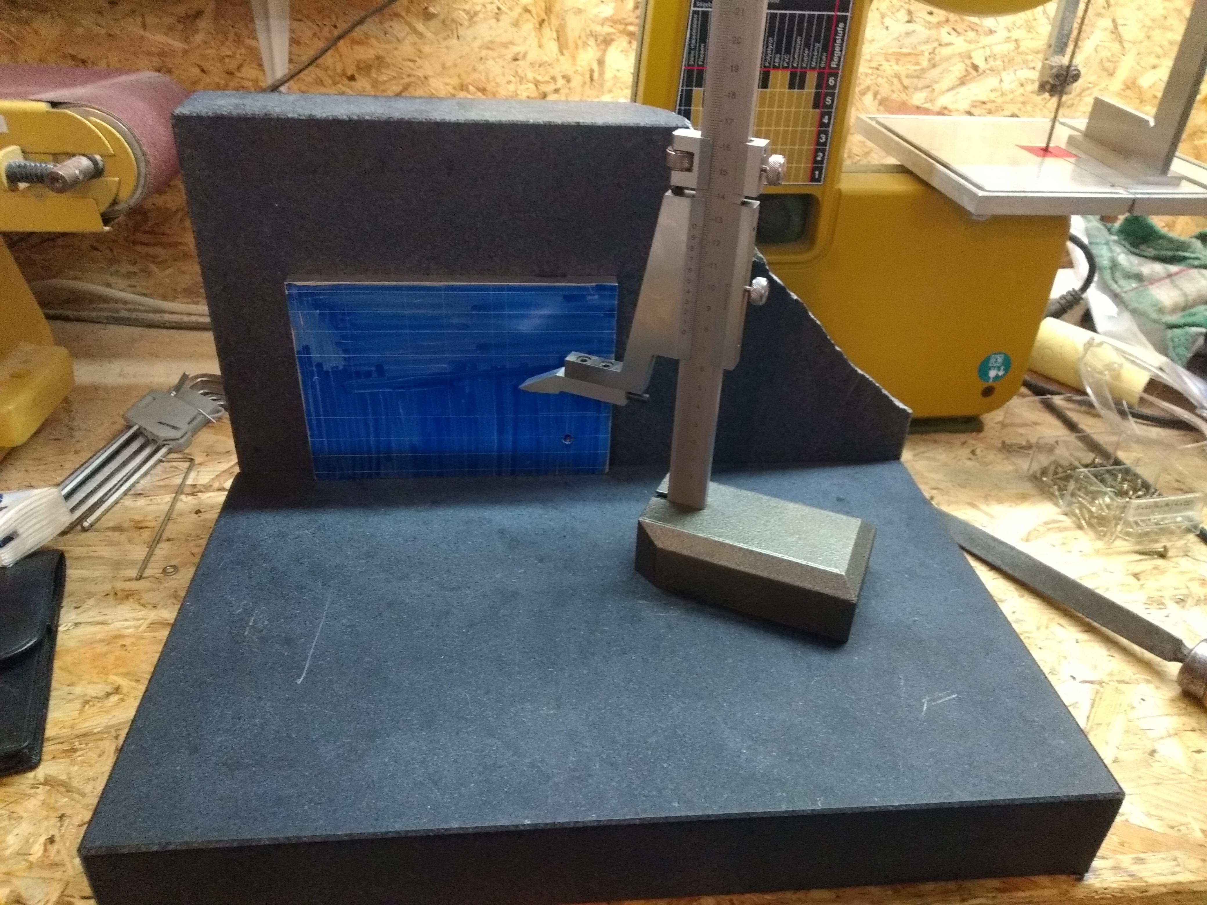
The hole positions are marked precisely using my small granite surface plate I bought just for that project. Together with a height gauge and shipping, it cost about 200 Euros here. I highly recommend investing in this equipment because not only is it really necessary for those kind of parts, but it makes working accurately on pretty much anything so much easier than with rulers and calipers.
I was “lucky” in some sense because the first plate was damaged during shipping, so I got a replacement, but was allowed to keep the broken one. Now I have roughly 1.75 plates, which is very handy to lay tall flat parts against. But watch out when using those cheap granite plates in that matter. The side faces look nice and smooth, but they might not be perpendicular to the main working surface. At least with my plates, this was the case. So they can’t be used as reference squares. I used shims to align them reasonably square, good enough for leaning parts against to scribe lines.
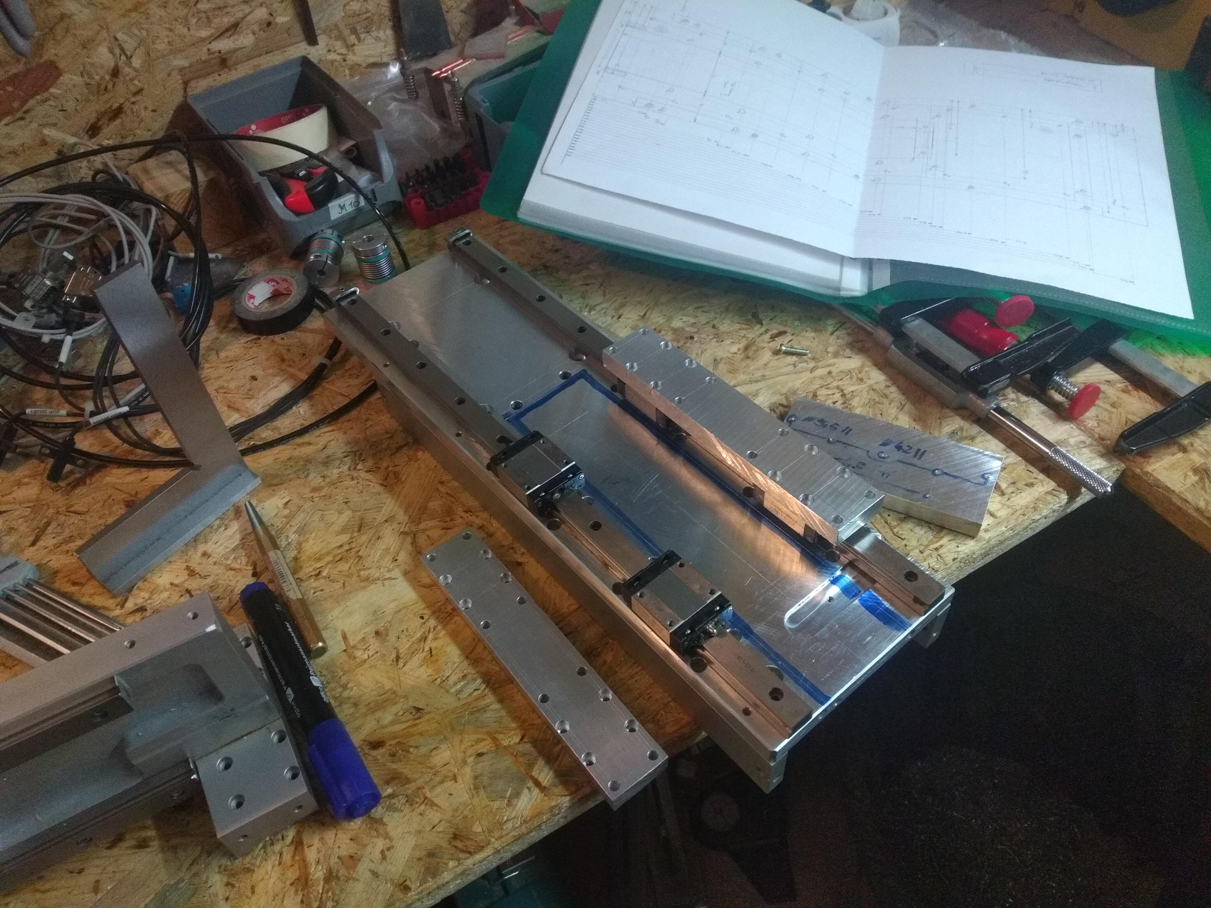
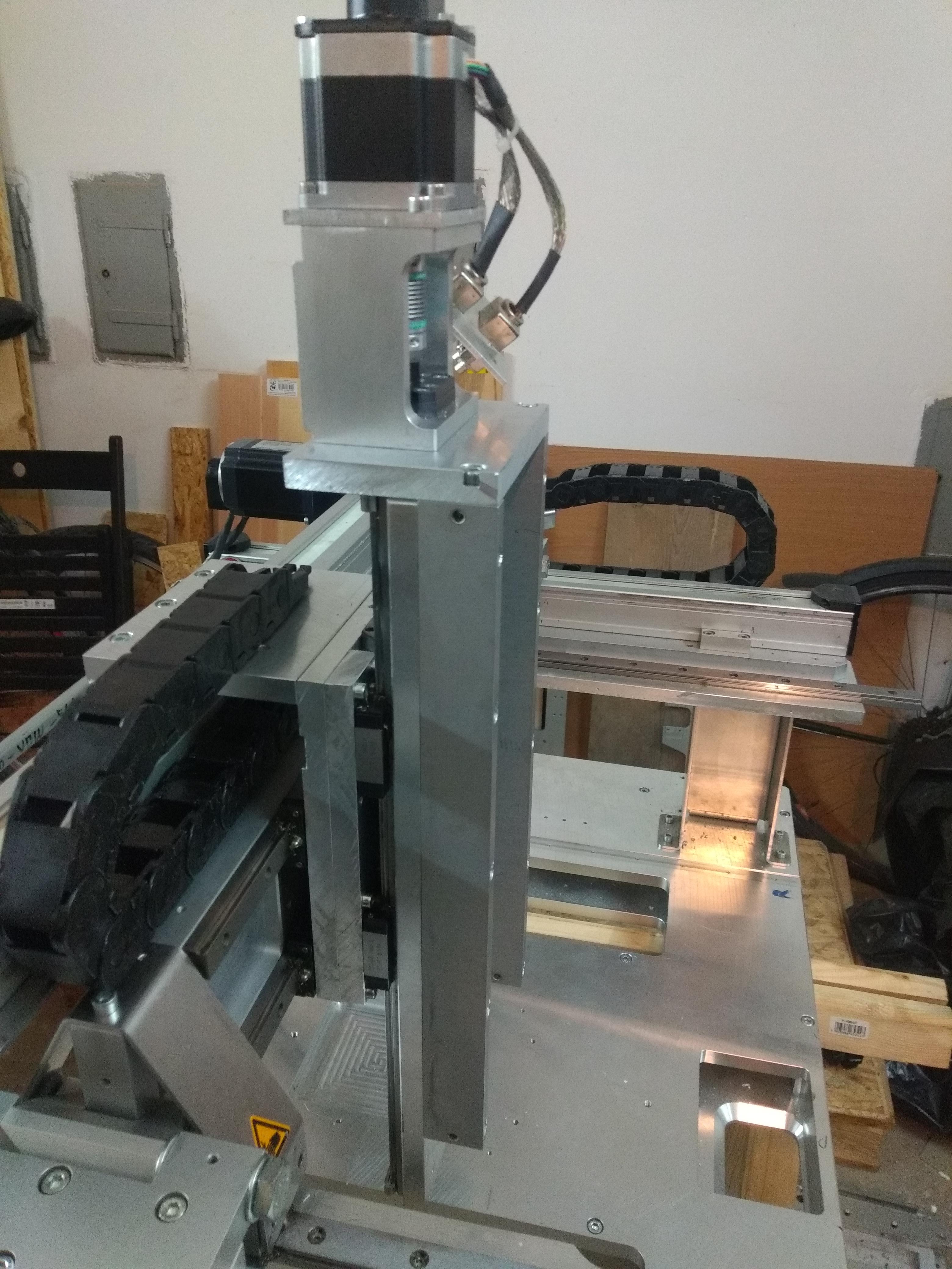
After producing a pile of aluminium shavings, the plate connecting x- and z-axis could be test-fitted. Luckily, the original aluminium bridge part is very accurate, hence the assembly runs nice and smooth without any shimming or adjusting.
The moving part of the z-axis is then also test-fitted after more drilling and cutting work.
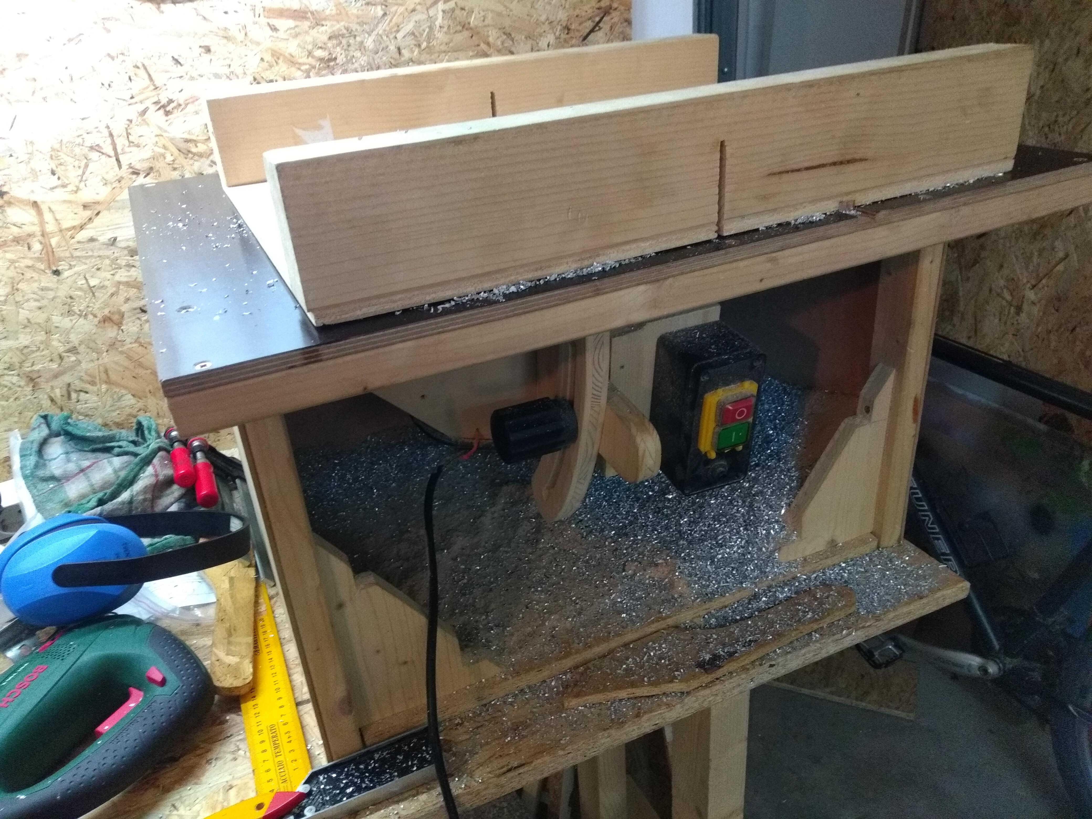
Note that in the above picture, a 3mm undercut outlined with blue marker is not cut yet. This is required to make room for the ballscrew nut later. Because I lack a proper milling machine to do this and the surface of the cut does not matter at all (its just clearance), I decided to try cutting it by hand with a woodworking router. Because of this violent procedure, a sturdy setup was made using all sorts of stuff lying around.
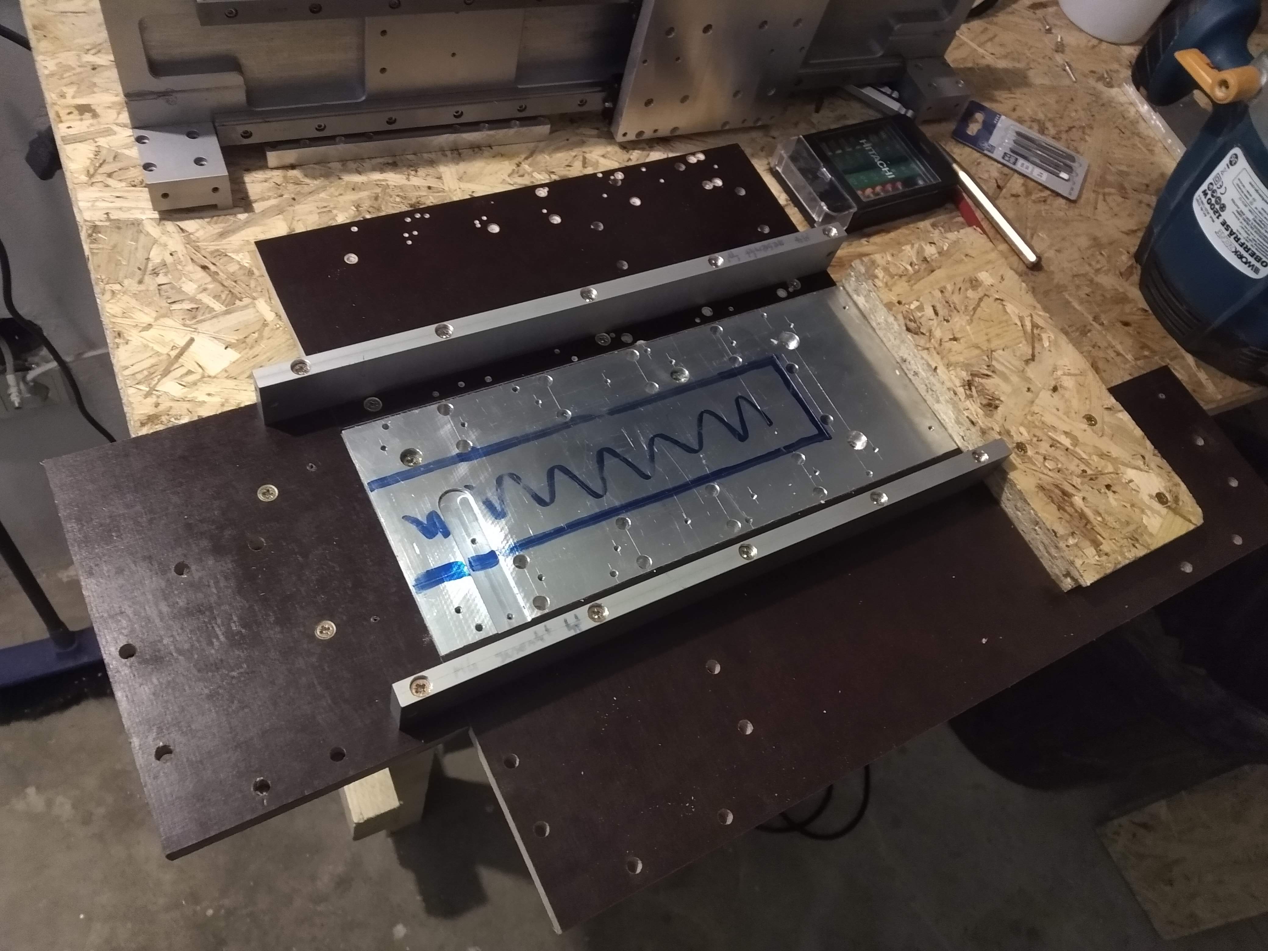
This worked, again, remarkingly well. I used an old carbide bit originally designed for wood, and increased to final depth in about 5 passes, taking roughly 0.6mm each. Additionally I paused every now and then and sprayed WD40. Without any lubrication, the router bit tends to clog up and behave very nastily. A bit of sandpaper to remove the burrs, and the undercut was done without a real milling machine. Unfortunately, I forgot to take a picture of the result of this milling operation, so you need to believe me this time.
The 1204 ballscrew for the z-axis is mounted between the linear rails. As the fixed bearing block, a part from the old screenprinter is used. For the loose bearing block, a custom piece is bored on the lathe for a loose fit o a standard 608 2RS ball bearing. The nut-holder is a standard part from ebay.
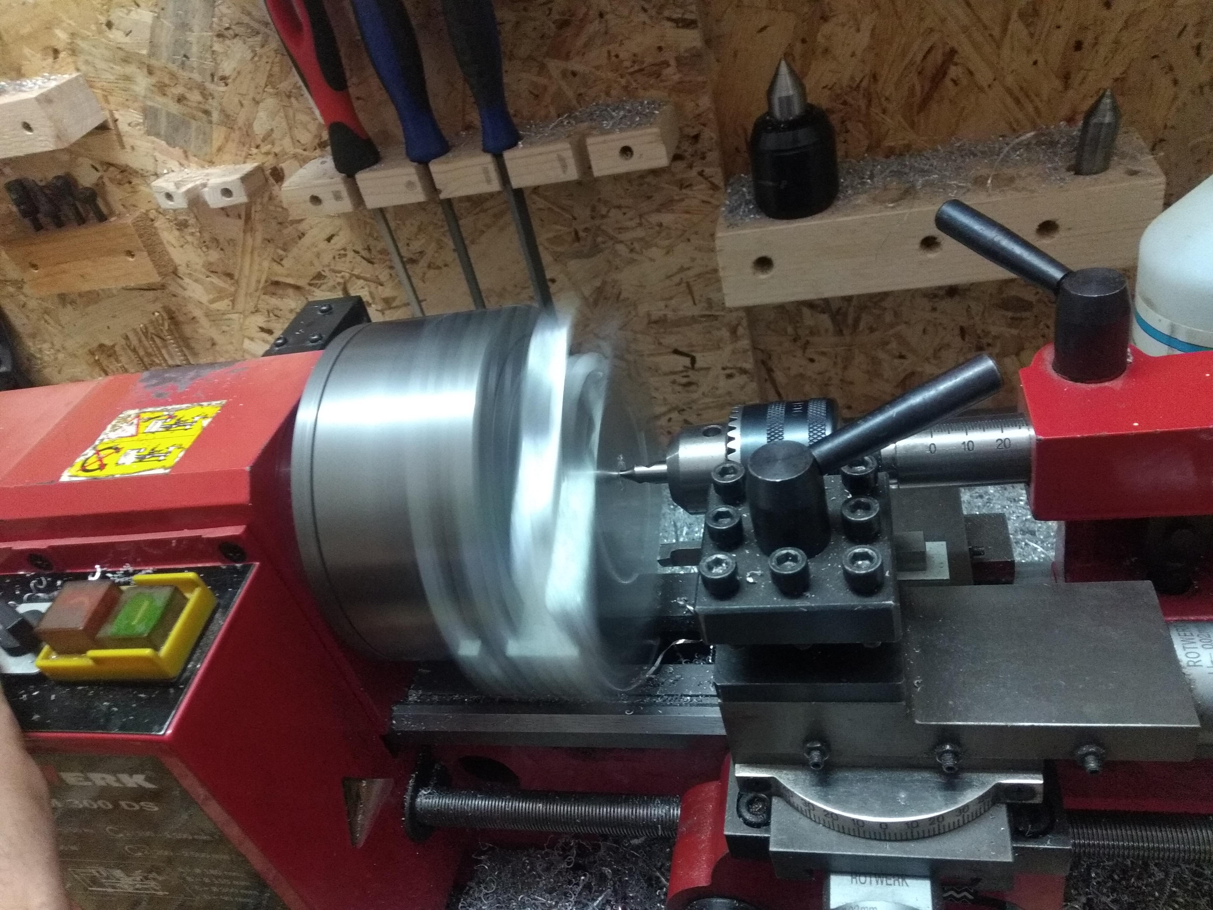
To later hold the milling spinde, two holders with a 80mm bore are needed. Those parts are just small enough to fit on my Rotwerk EDM300 hobby lathe, so that was straight forward. Later, they were slit on the bandsaw to be able to securely clamp the spindle with a screw.
At this point, the z-axis is basically complete.
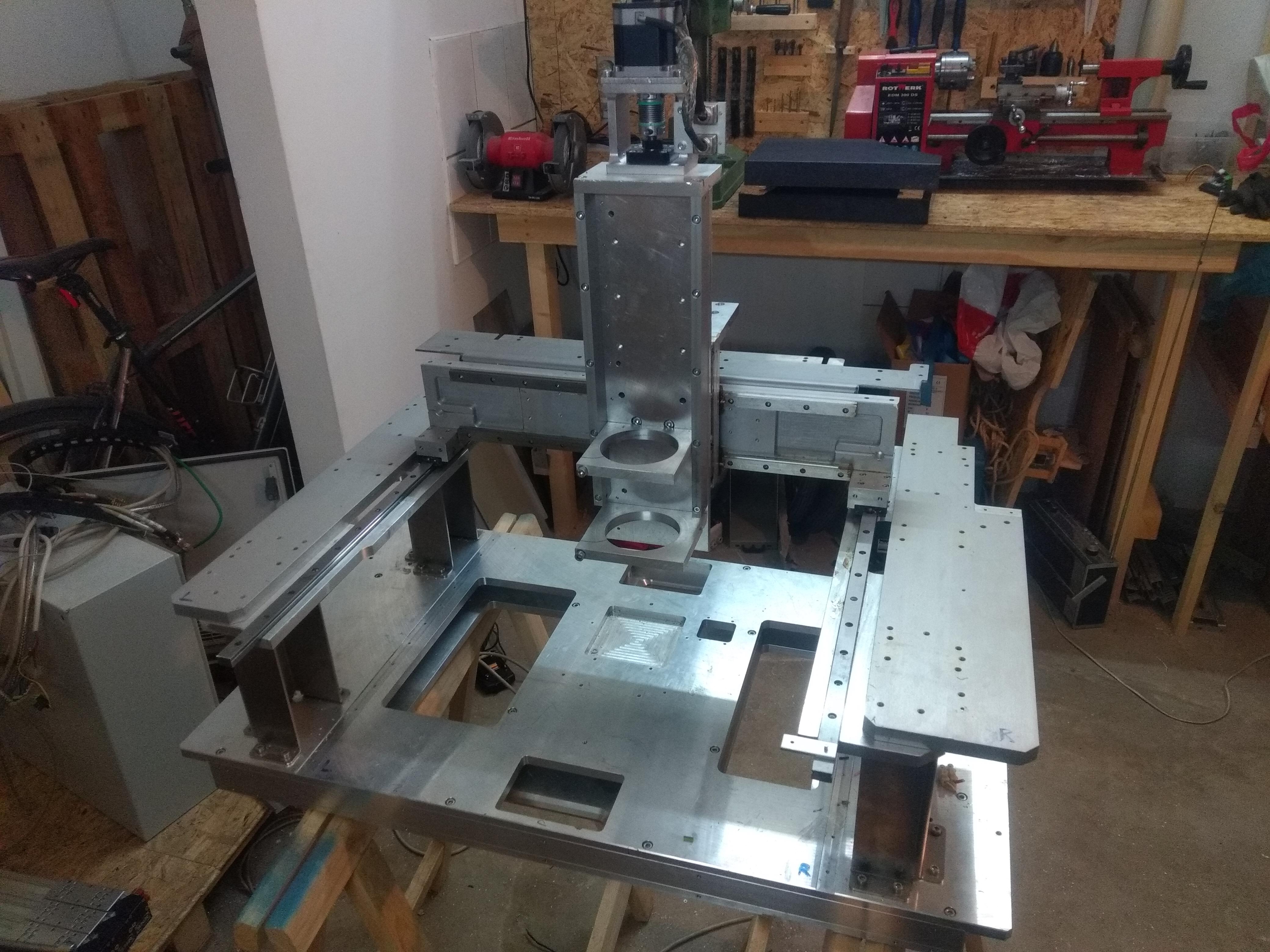
See the next part for the drives of x- and y-axis.