CNC from Screenprinter - Part 6
CNC ·Electronics and control system
In this part of the series, the electronics and control PC are described. Find the previous part here. On the original screenprinter, there were four 1.8° stepper motors, two stronger ones with about 2Nm and two smaller ones. The big motors are reused for x- and y-axis, one smaller motor for z. All motors are equipped with 500PPR encoders of type HEDL-5600 and a classic A,B,I interface. This allows to operate the machine in a closed-loop manner, which is very helpful.
Arduino - or rather not.
In the first try, I intended to use an arduino mega with the popular grbl motion controller which does not support encoder interfaces. Together with a couple of cheap stepper drivers from ebay based on the TB6600 chip, this should become a very cost-effective solution for this CNC-experiment. It did end up in the trash, however. A couple of reasons for that: First, the TB6600 stepper drivers are absolutely unusable in my opinion. The manufacturer claims currents up to 4A, but I never saw much more than 1A flowing, even tough it was configured for 4A. This is, at least in my understanding, because of very poor PCB-layout and grounding issues. You get what you pay for, I guess.
Second, the arduino as motion controller. While grbl itself might be an ok-ish solution if your demands are not too high, the G-code-sender software I used was buggy and would sometimes not react, sometimes rapidly drive the machine somewhere. Totally unusable for a CNC machine. Also, the whole concept of using an arduino as a motion controller is doomed from the beginning in my opinion. And I must say, I pull my hat for the people that managed to fit all this functionality in this small Atmel chip. But the real question is: Why would you even want to do that if you have much more powerful processors available for cheap these days.
Anyhow, the control was build, switched on, and torn to pieces again after half an hour of fiddeling with it. Sometimes, that’s how it turns out.
LinuxCNC and MESA 5i25
I always wanted to do something with LinuxCNC, because, you know, it’s free and powerful and very flexible, and it’s Linux! LinuxCNC is a full machine controller that runs on a PC. It means that LinuxCNC itself keeps track of the axis, generates step pulses and runs the servo loops. This is contrary to other implementations, where all the “low-level” machine tasks such as step generation and servo loops are carried out in hardware on a microcontroller, FPGA or custom DSP and the PC is basically just the GUI and maybe a translator from g-code to some intermediate form.
Of course, PC programs are known for rather doubtful real-time performance because of complex memory management, operating system routines and such. So the question is, how is it even possible to implement a real machine controller on a PC? First, LinuxCNC is per-se an application, but it is actually rather a whole operating system because the kernel of the underlying Debian is modified in such a way that some task are executed in a controlled interval - no matter what. This task is used for the servo loops.
But even still, a PC is not able to generate microsecond-accurate timings required to drive stepper motors fast and smooth. That’s where the popular MESA cards come in. Those can be installed in a PCI slot and provide a bunch of IO-Pins from an FPGA. As they come out of the box, the FPGA is blank and the user can do with it what he wants. The manufacturer, however, provides an extensive selection of VHDL projects on its website that can be opened with the IDE from the FPGA manufacturer Altera. There are many precompiled FPGA configurations available on the internet, for example for all the extension cards offered by MESA.
If you do not use an extension card like I did, however, you need to roll your own FPGA configuration. A driver called HOSTMOT2 allows LinuxCNC to access resources provided by the MESA card. Those resources can be step generators, encoder counters, PWM generators and so on. Using the provided examples and other projects from the internet, it is not too hard to set something up with three step generators, three encoder interfaces, one PWM generator and a couple of IOs for the limit switches, as was needed for this project. I can warmly recommend Talla83, a german youtuber and CNC-enthusiast, who shares extensive materials on how to work with LinuxCNC.
Anyhow, the FPGA now provides the lowest level tasks such as generating step pulses with exact timing. All of this together makes for a CNC-controller with remarkable performance, at least in the hobby world. You notice the timing accuracy by how smooth the axis move. They are so much quieter than with the arduino!
Control Electronics
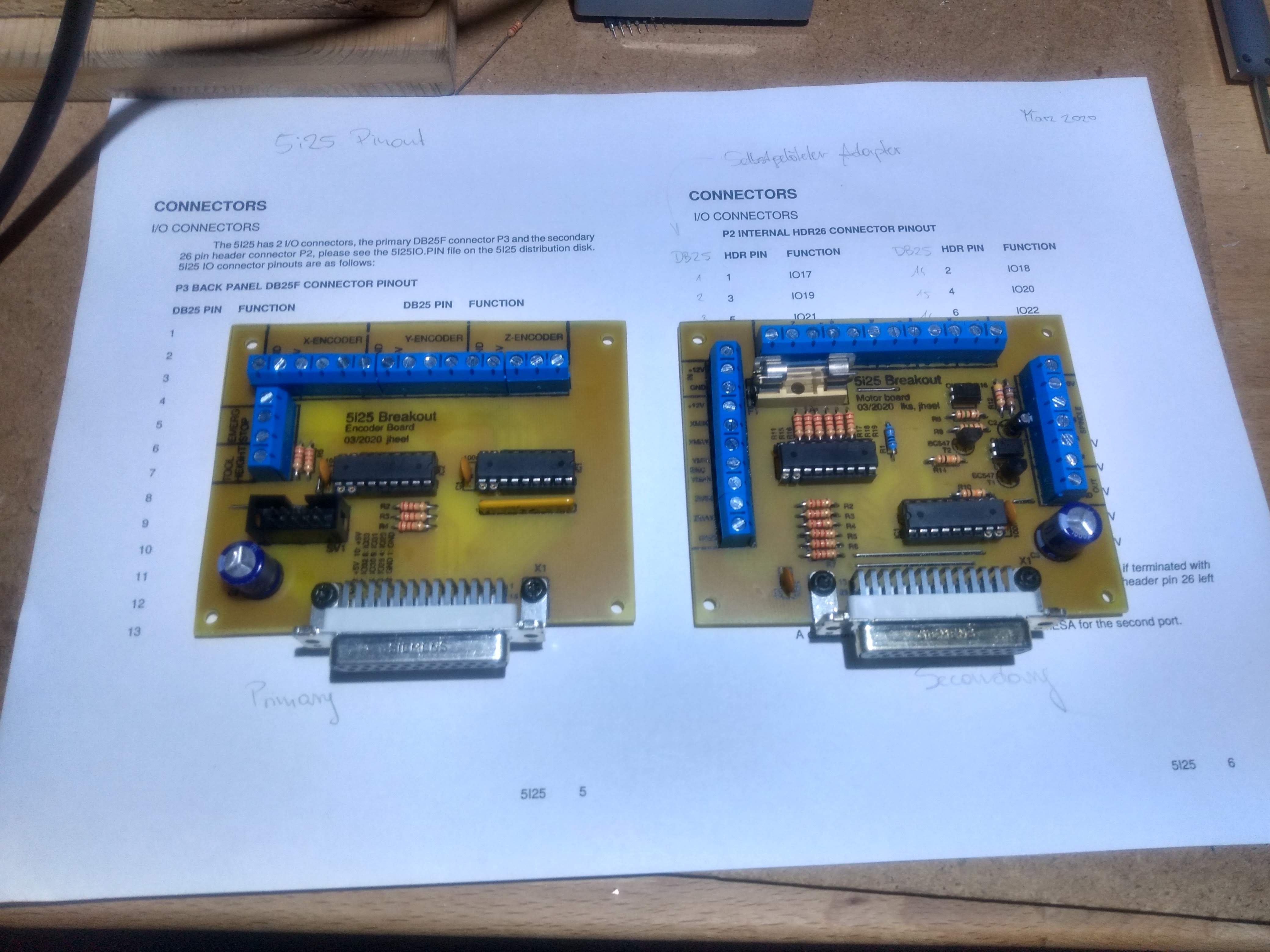
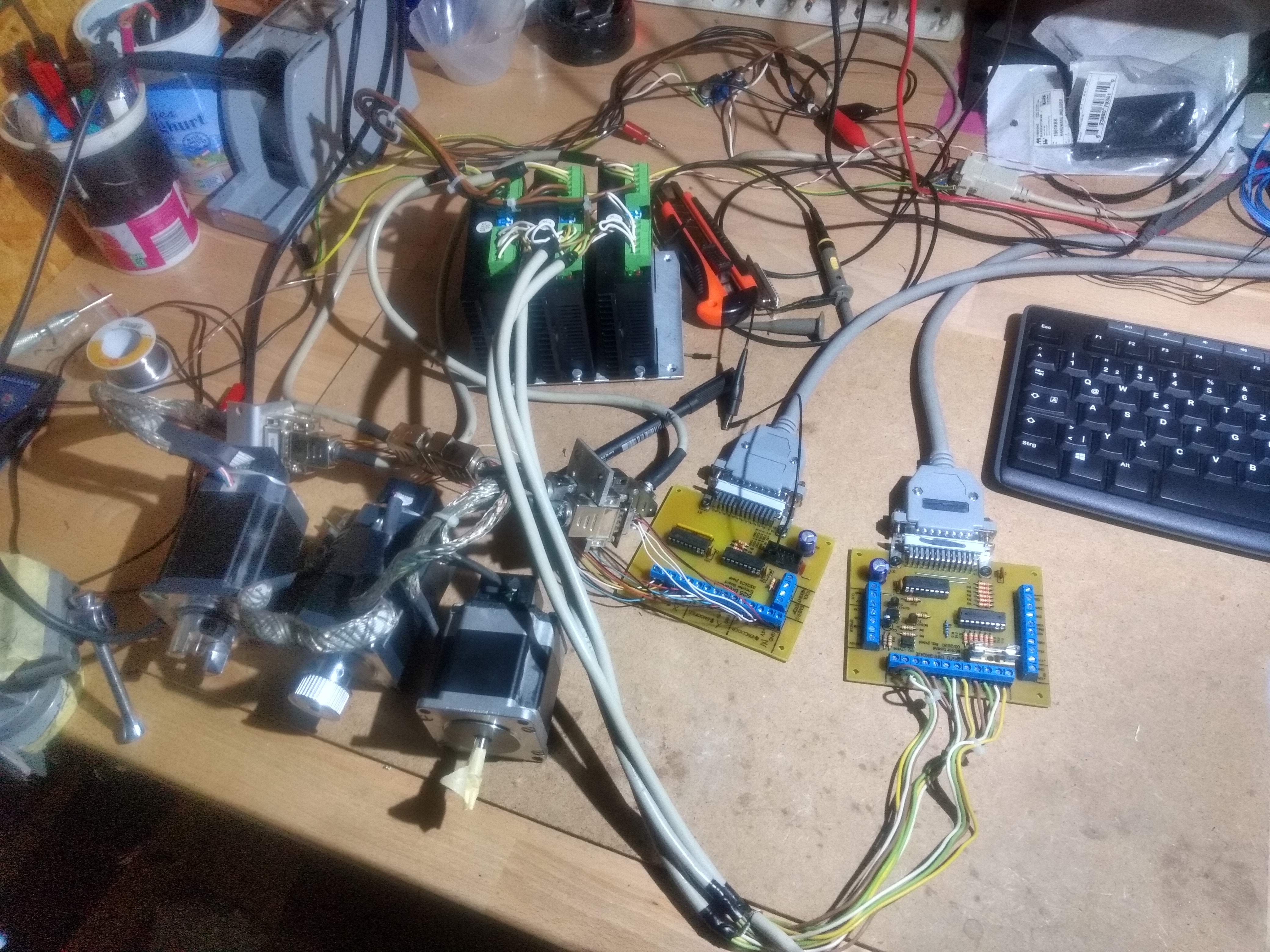
To interface the stepper drivers, encoders, limit switches and so on to the delicate FPGA pins of the MESA card, two breakoutboards are created in Eagle and fabricated with my etching bath. The cards mostly contain connectors, but in some places, ULN2803 darlington drivers and CD40106 CMOS inverters are used as buffers to protect the MESA card.
As the TB6600 stepper drivers were too cheap, I bought some based on the DM452 chip for about 30 euros per piece. Those are a completely different level in terms of built quality and performance. They are able to generate the full 4A of current and the motors just run much smoother. In other words: If I am ever going to buy stepper drivers again, I will get those because the cheaper ones are just not worth the time, really. With LinuxCNC installed, it took surprisingly little time until the motors would run the first time.
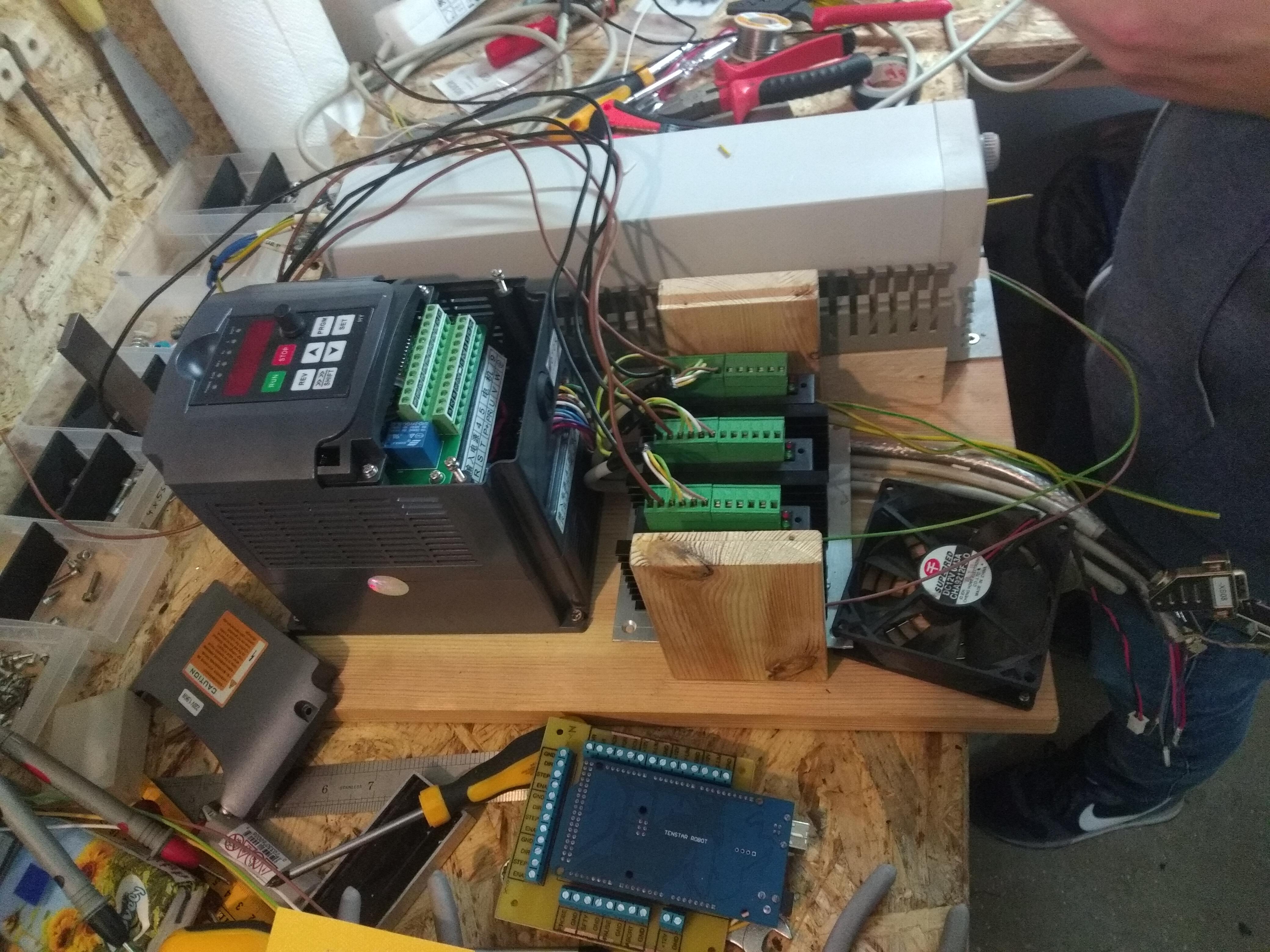
The control electronics is quickly assembled by screwing various pieces from the screenprinter machine, the homemade breakoutboards, the DM542 stepper drivers and the spindle inverter on a wooden board. At some point, a dedicated electronics cabinet would be nice, but let’s see when I find time to build one.
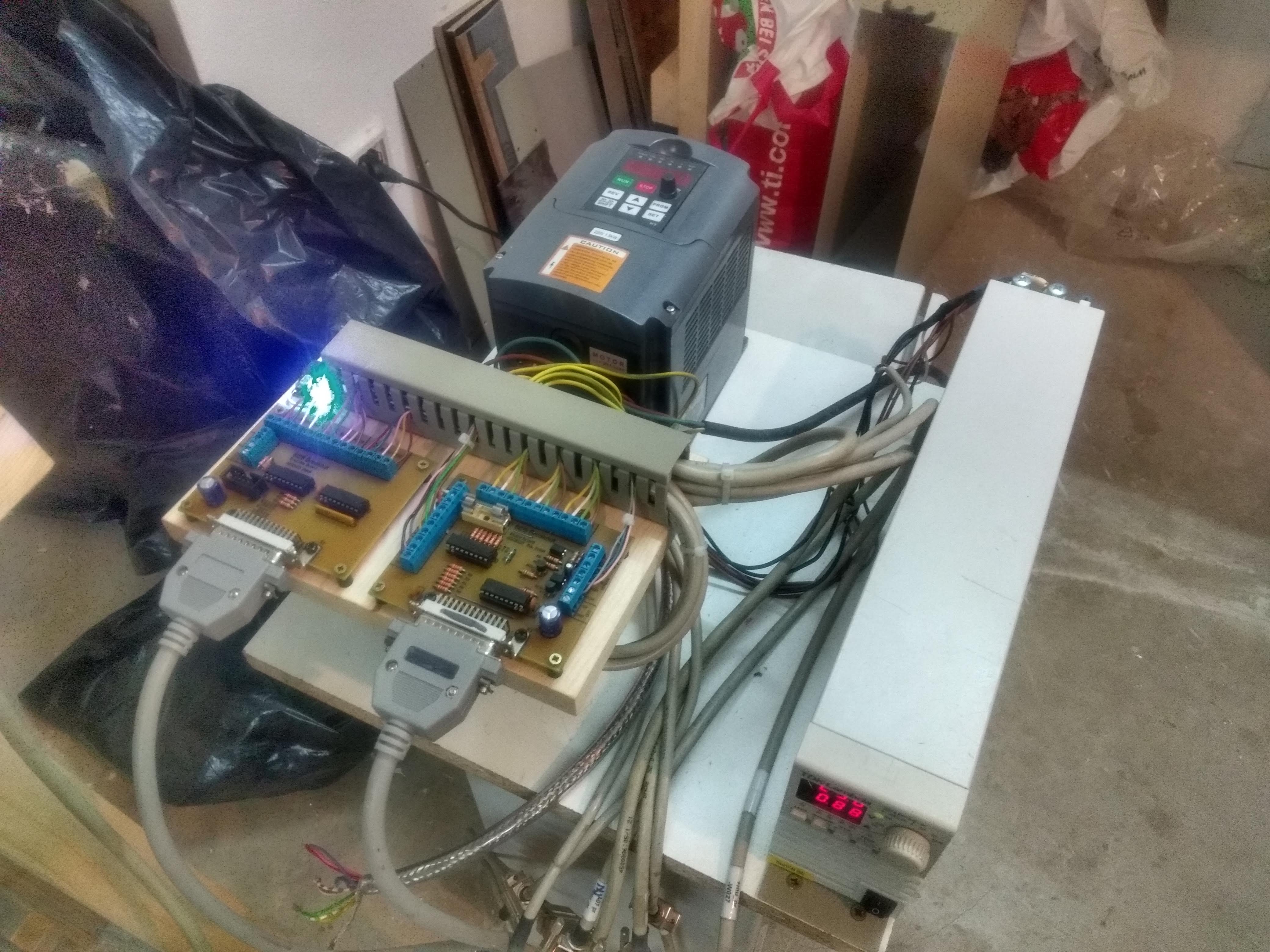
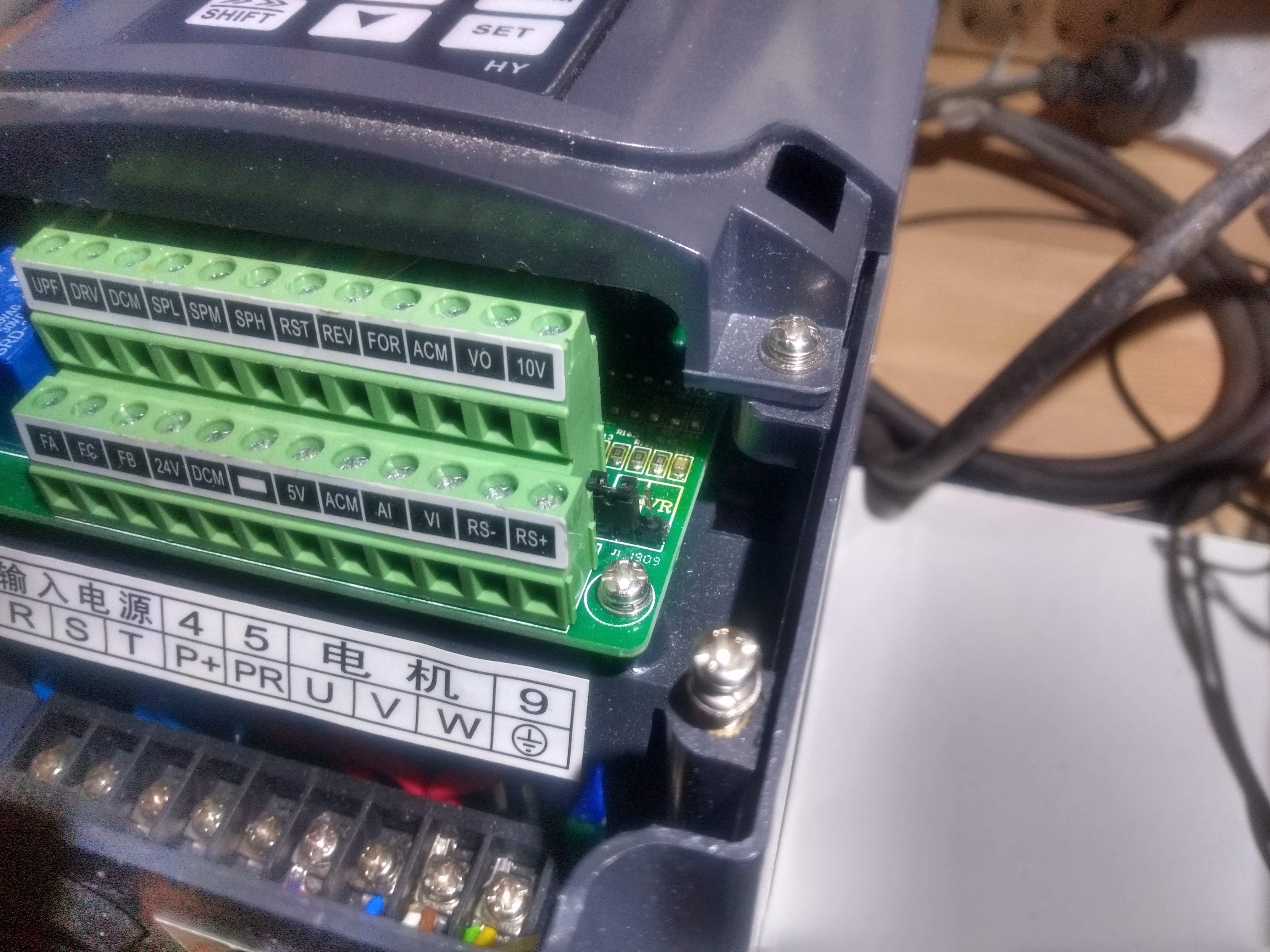
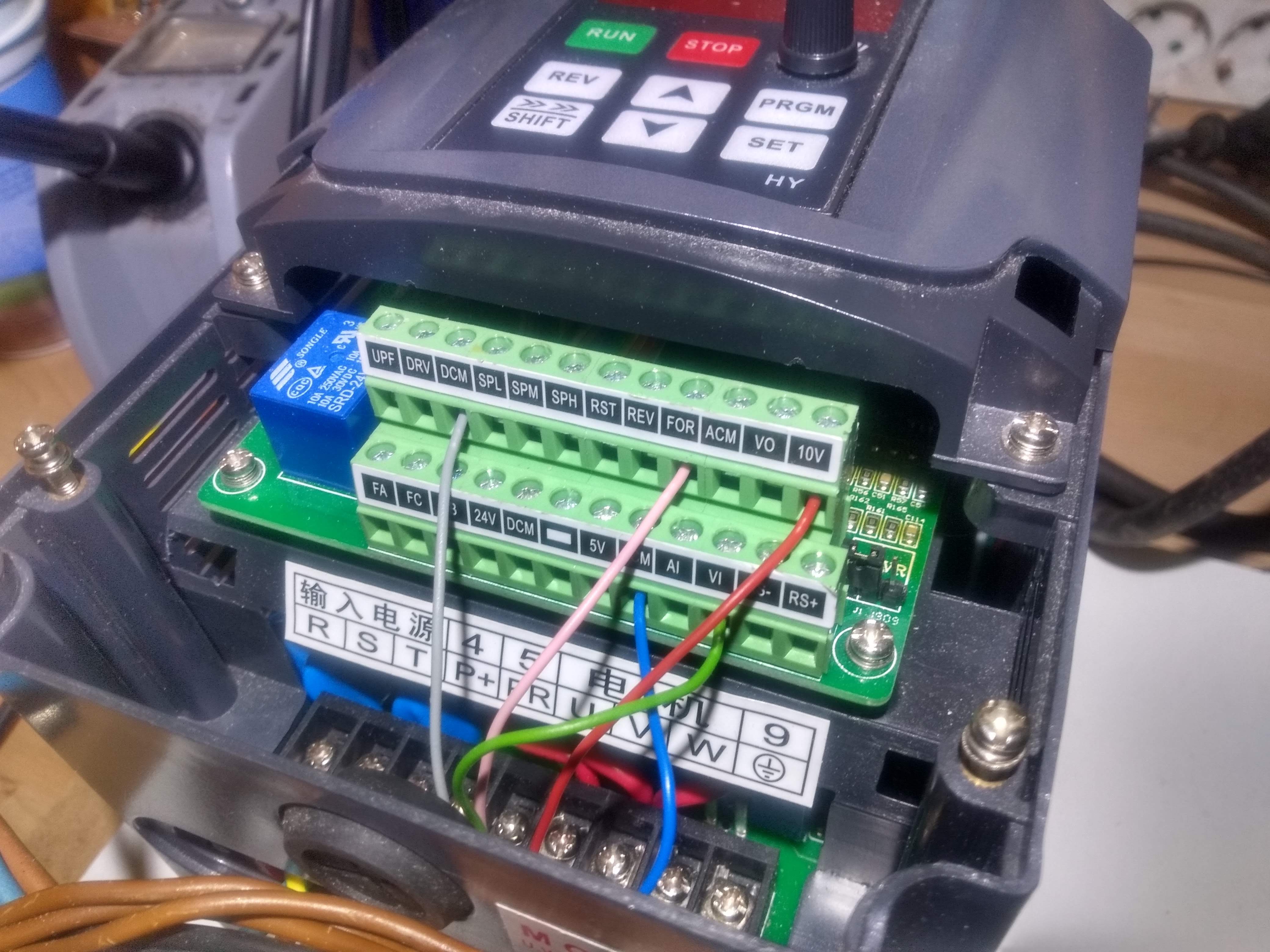
Spindle inverter interface
(Some information about configuration of the huanyang inverter will be added here.)
This is the final part of this blog series. For the end result, see the project article.