Repairing a BOSCH AL 3640 CV battery charger
Electronics ·Introduction
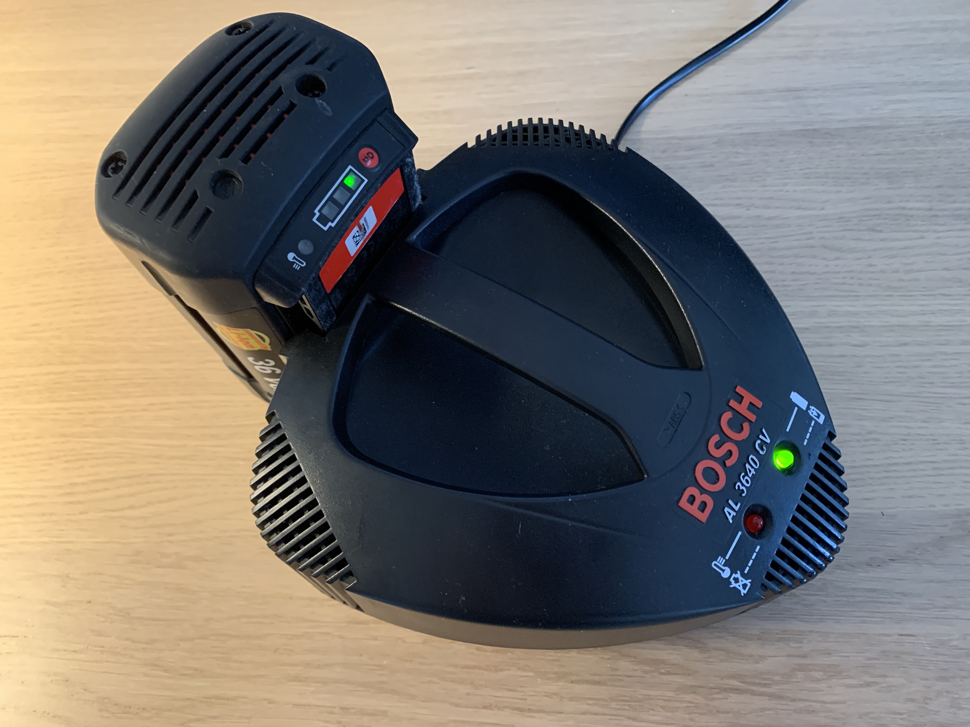
Working full time, doing some sports and social activities does not leave much time for electronic projects. However, occasionally it is still nice to mess a bit with traditional electronics, such as to do a repair job. Specifically this time, we are dealing with a BOSCH AL 3640 CV charger for 36V lithium batteries that can be used to power a lawn-trimmer, for example.
The problem
… is quite simple to formulate: It does absolutely nothing, no lighs, no sounds, no output voltage.
A quick look inside
Upon unscrewing the cover, a switchmode power supply of fairly standard construction appears.
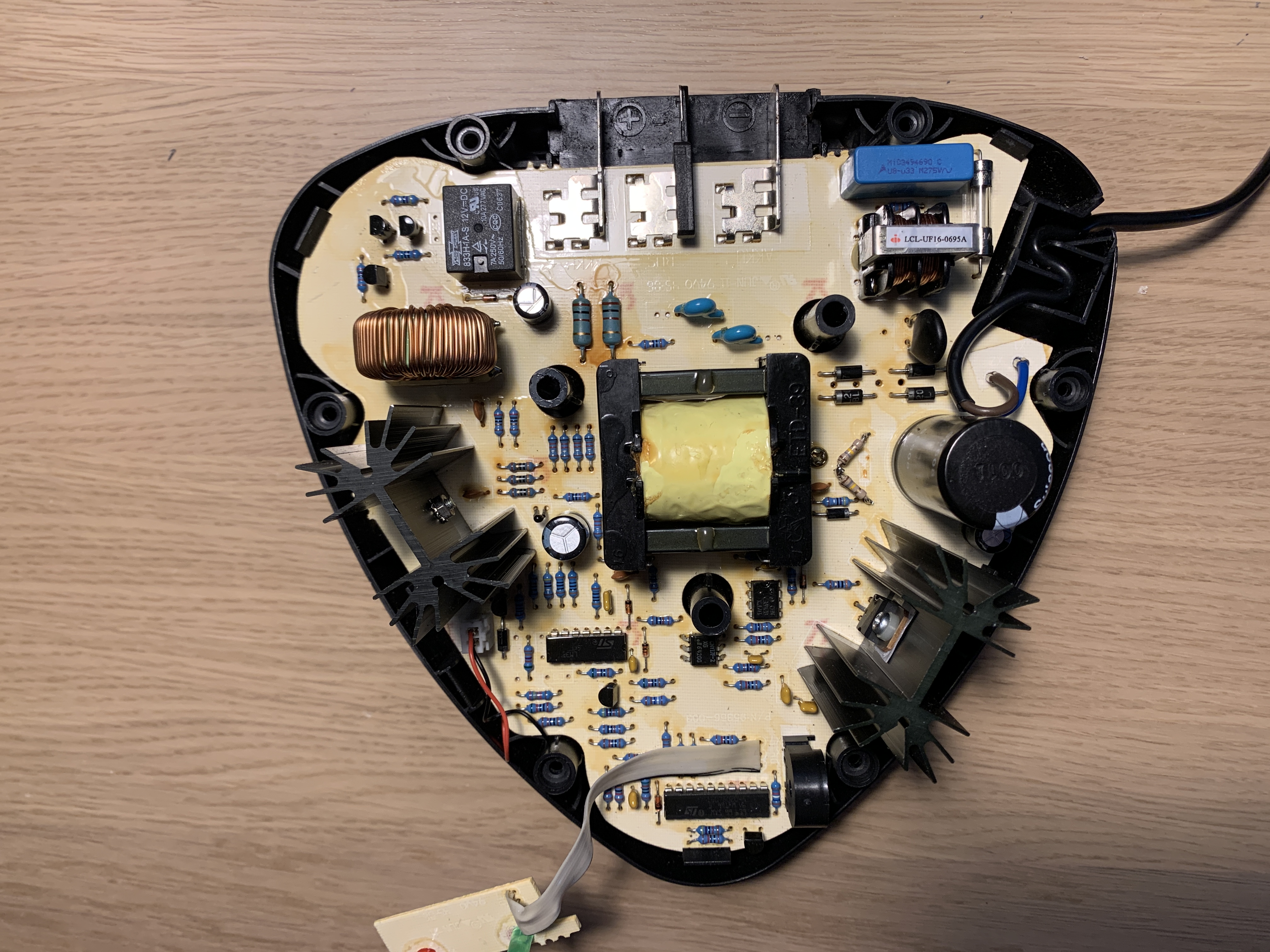 It contains an input rectifier, a switching transistor to put AC through a transformer, an output rectifier and some control circuits around it.
A quick check with the multimeter reveals that the input rectifier is fine, there are about 320V across the primary buffer capacitor. But the switching MOSFET (P6NK90Z) does nothing. Is it broken? Could be, but it also does not see any drive signal on its gate, so even if it was fine, it would do nothing. When it does not receive any drive signal, something with the switch mode drive circuit is presumably wrong. At this point it starts go get a bit more complicated.
Available information
Just googling through the internet, you can find some information about this particular device fortunately. Someone went to the effort of reverse-engineering the schematic of the primary side. A common fault seems to be a 180kOhm power resistor that acts as a startup help for the supply. It is constantly under about 300V DC strain and hence might fail after some time. Mine measured 200k instead of 180k, which is not very drastic, but might be a sign of aging, so I replaced it with a group of four 180k 0.25W resistors, just to be sure. They are located here:
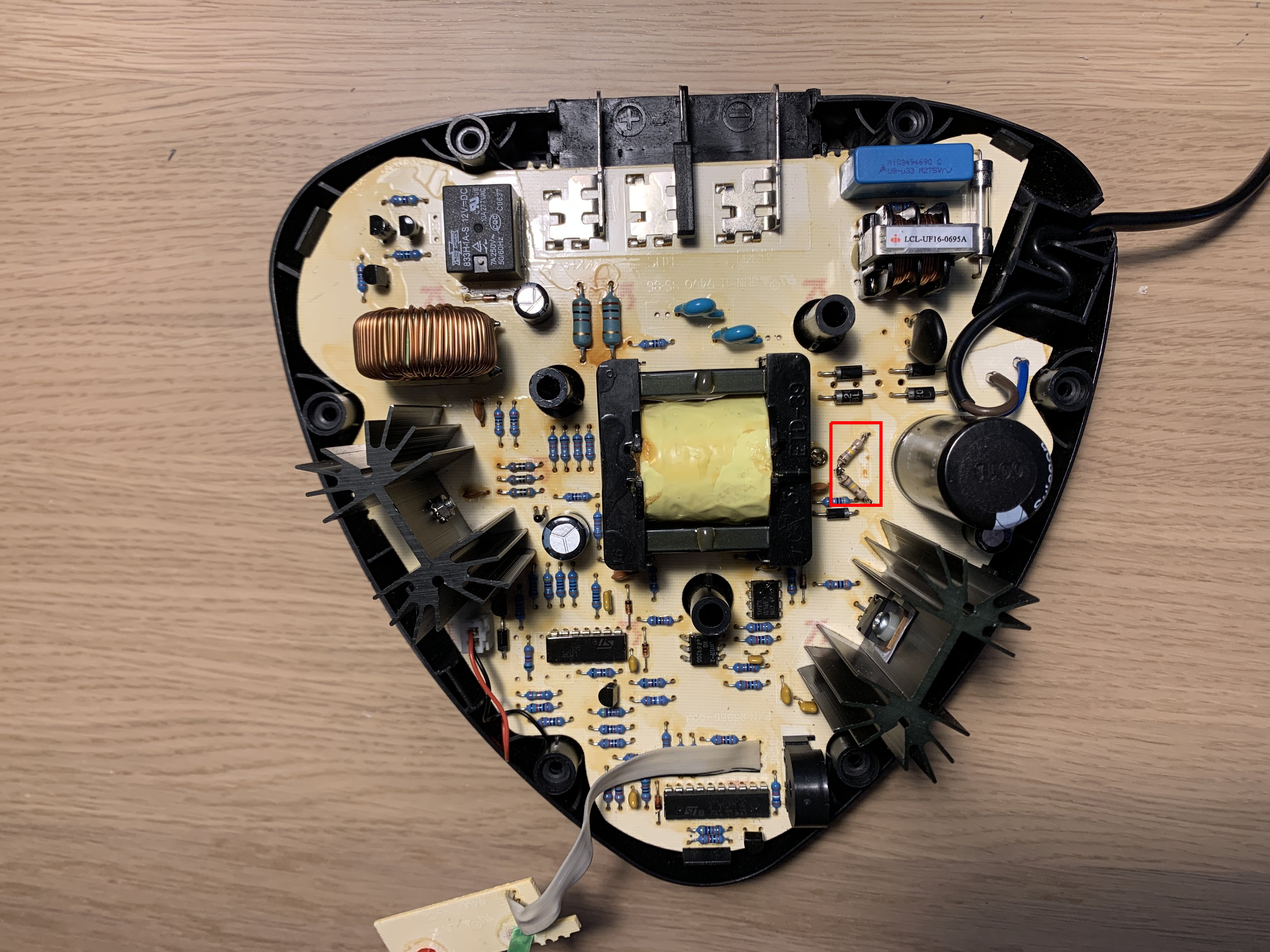
It would in fact explain the observed behavior quite well: No startup resistor, no sign of life at all. Unfortunately, in my case, the fault persisted absolutely unchanged.
Looking deeper
Upon roughly checking the surrounding passive components and diodes, the next suspect is the PWM controller itself (UC3842D from ST microelectronics). If it was faulty, it would explain the same behavior. However, simply replacing it requires a) to order it and b) leaves me with the bad feeling of not knowing why it actually failed, so the replacement might just fail as well after some time.
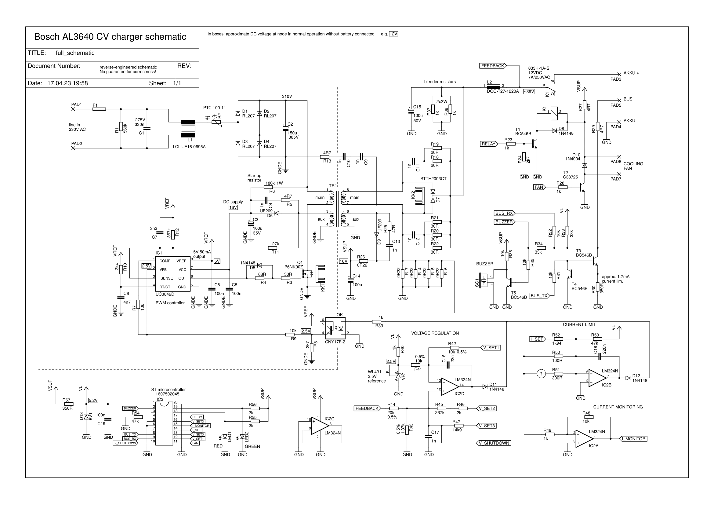
At this point, I thought it would be nice to understand a bit better how the charger works. Because it is a single-sided PCB with not too many components, I decided to reverse-engineer the whole schematic and thereby share what I learned to aid with some future repairs of other people. Here it goes:
 Download PDF
A quick disclaimer: Although I spend a few hours on this, I cannot guarantee the correctness of the schematic. Also, the label names etc. are my guesses of course.
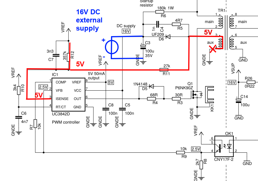
The circuit is actually pretty neat: First, the 180k startup resistor raises the DC supply of the switchmode controller to about 16V. The feedback from the optocoupler should be about 0 at this time, so the PWM controller starts giving out pulses to the switch MOSFET. By doing so, it provides its own supply through an auxiliary winding and hence does not rely on the startup resistor anymore. After some time, the voltage at the output will have risen high enough that the voltage regulation loop (IC2D) starts pushing some current through the optocoupler, which chokes the PWM controller and hence it will find a stable operating point. A current limit is also implemented with some shunt resistors, which can overrule the voltage regulation loop by an analog OR (two diodes), if you want to say so.
To understand why the PWM controller is not doing anything, it would be nice to take a look at the primary side circuit with the oscilloscope. No isolation transformer was at hand, so I decided to just power up the DC supply of the PWM controller and leave the mains unconnected. Looking at the above schematic, this works without harming anything.
The fault
To my surprise, the PWM controller was not entirely dead, one could see its oscillator at around 100kHz at pin 4 (RT/CT). So why is not outputting anything? The answer is quite simple: The solder connection of the auxiliary winding to ground is bad! Its impossible to see by eye, but the lack of DC path caused the whole current feedback network to be pulled to 5V by R12, which makes the PWM controller belive there is a huge current going in the coil, so it completely shuts its output.
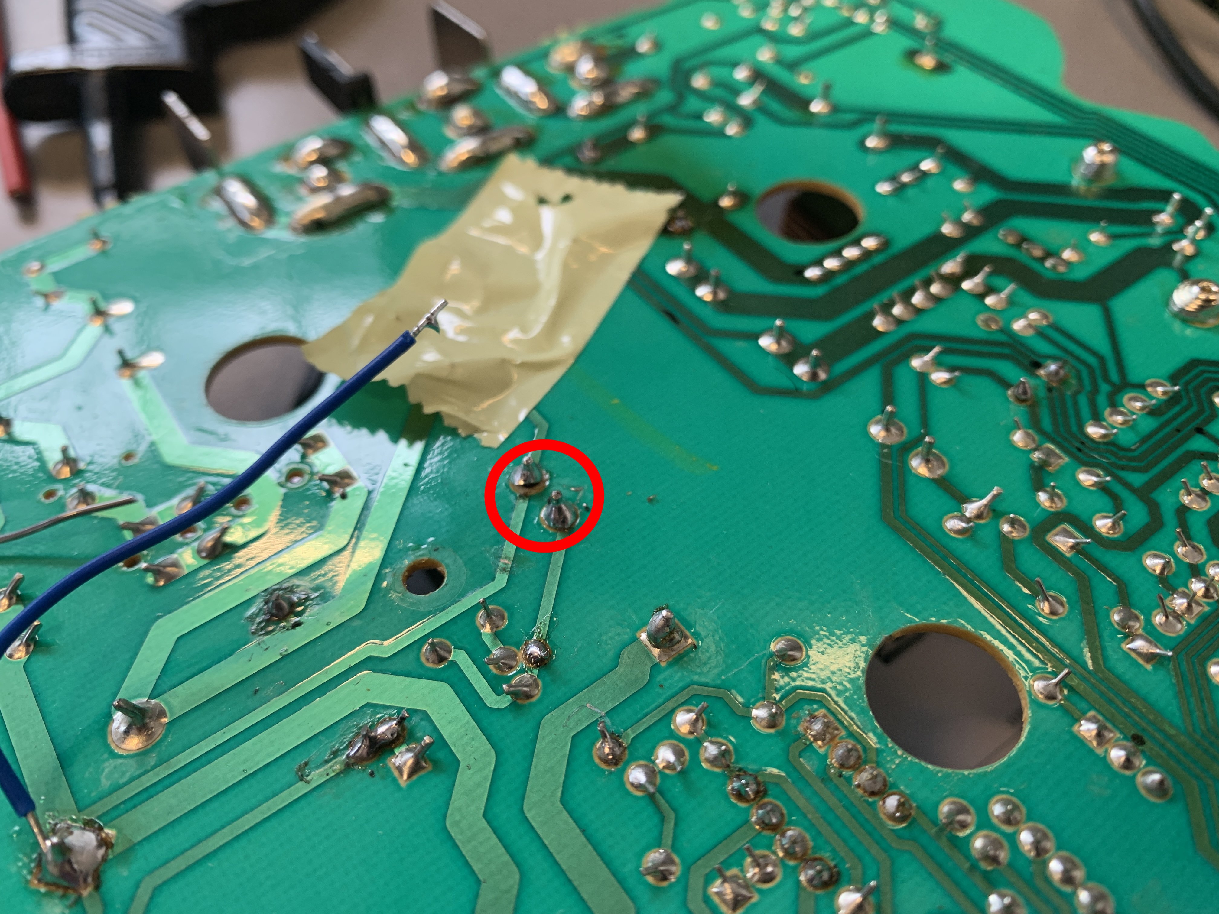
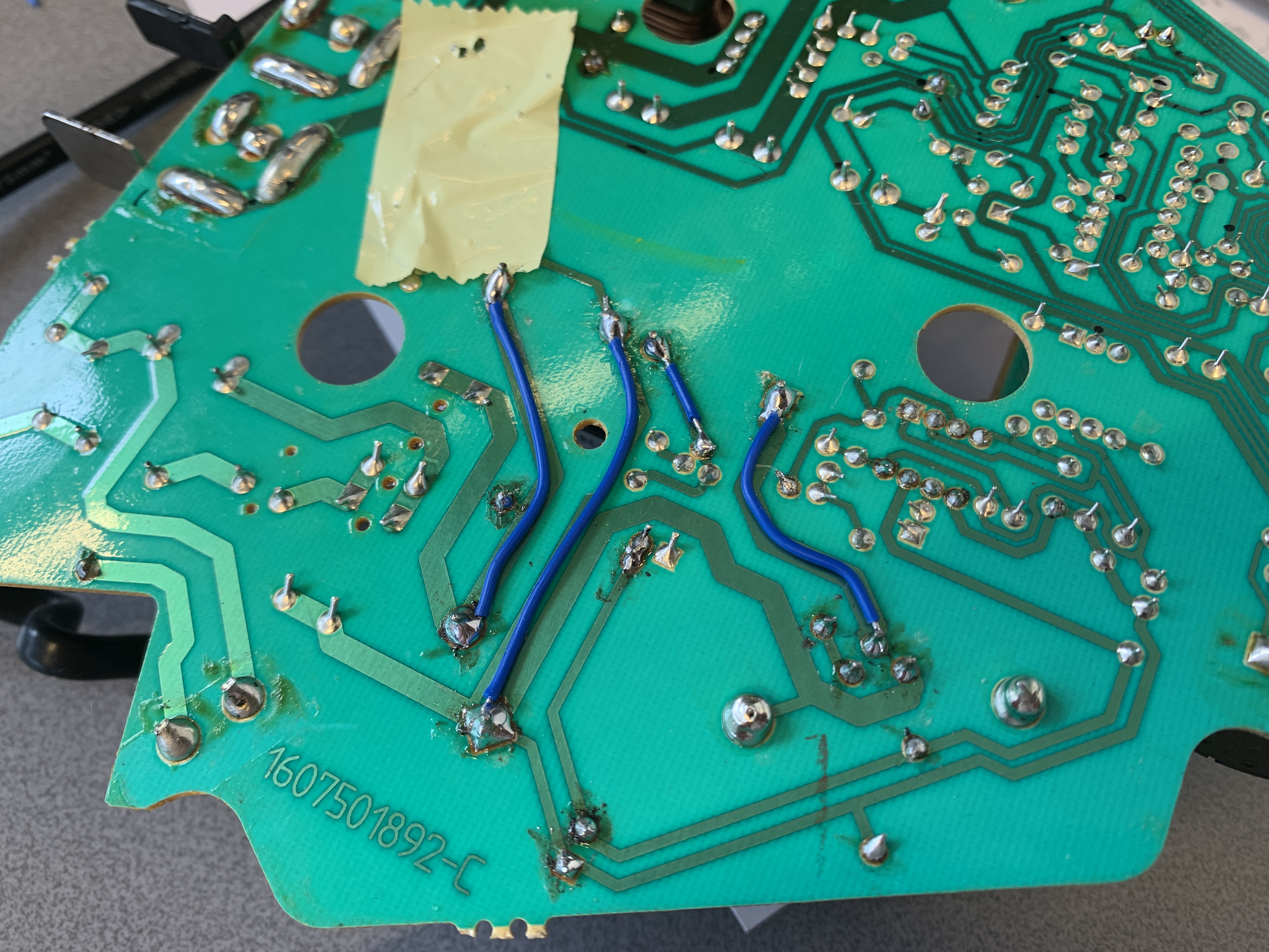
This point of failure is also quite plausible: Its a portable charger that gets thrown around when carrying, and the transformer is quite heavy, so its solder joints see a lot of stress and one finally failed. The fix is easy: scratch the traces blank and bridge the gap with solder. Additionally, I added some wires, which should fix this for eternity, just in case.
Summary
By throwing around the portable charger, a lot of stress is put on the solder joints of the heavy main transformer, so eventually, a bad connection developed. This caused around 5V on the current feedback path of the PWM controller, hence it never turns on its output, even though the PWM controller IC was unharmed.
After fixing the solder connections, it works and charges batteries again.