Homebuilt electric scooter
Electronics, Mechanics, Projects ·Introduction
It goes without explanation that contraptions with the potential to propel oneself with have a very high fun factor. This project was started around an old 250W DC motor that a friend of mine found somewhere in the trash. We decided to motorize an old children’s scooter with it, although we did not want so spend so much money on it.
The build
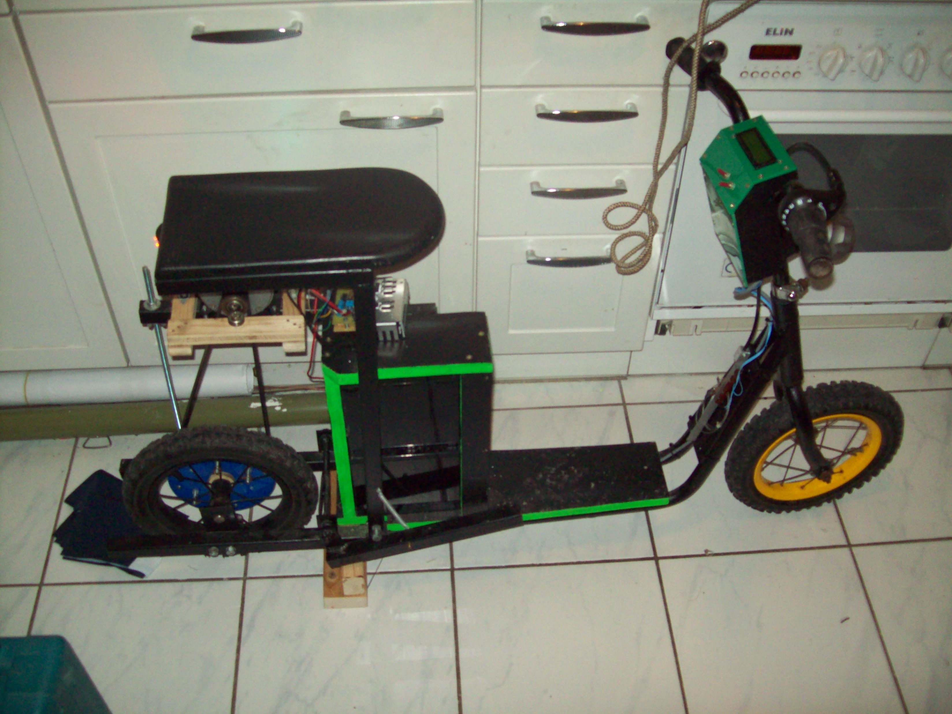
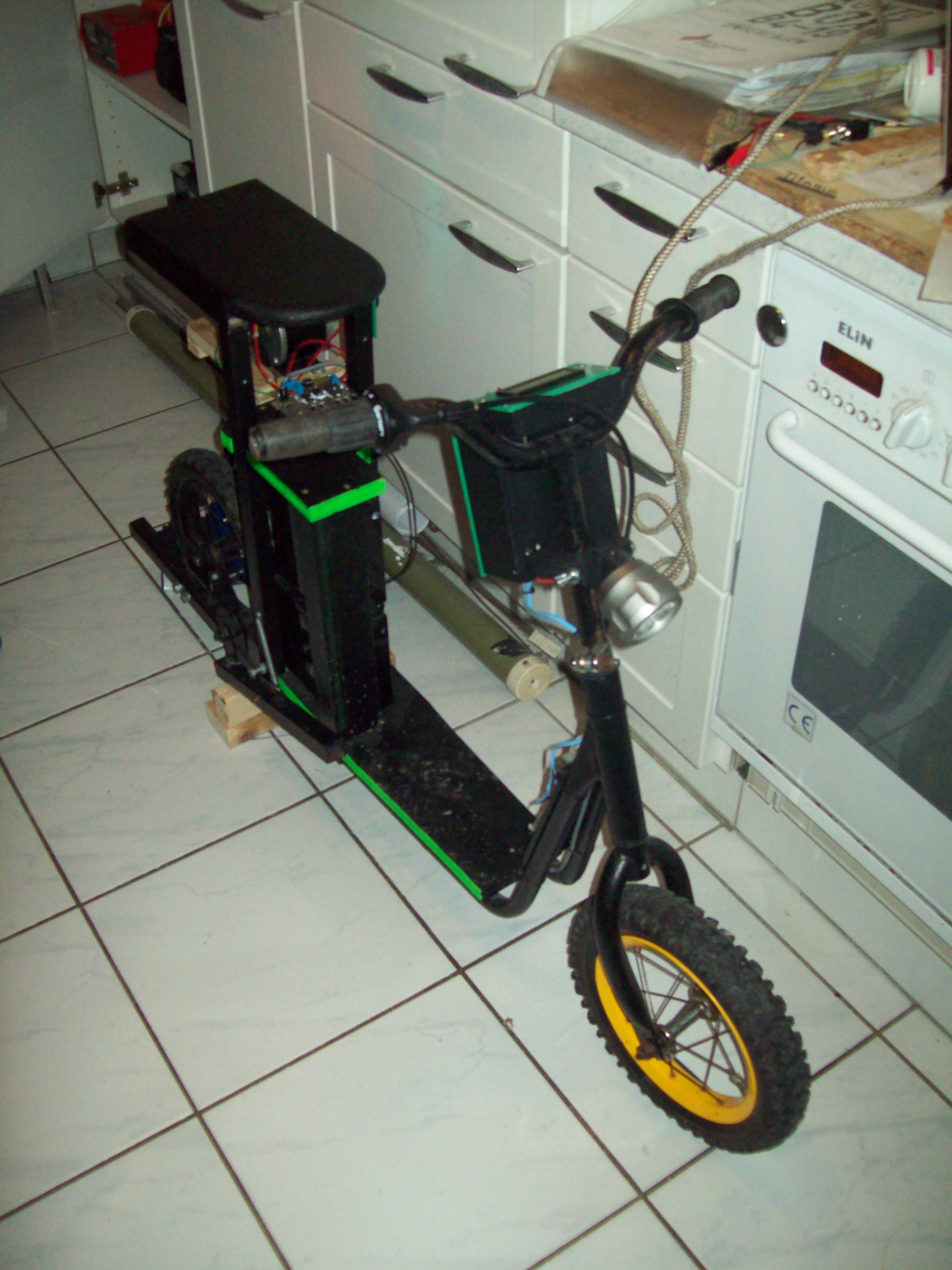
The basic “power train” consists of the motor driving the rear wheel with a flat belt from a broken exercise bike. The small pulley is also from this exercise bike and conveniently only transfers torque in one direction of rotation. The large pulley is turned from wood and plexiglass on my small lathe and transfers its torque directly to the spokes of the wheel. The wheel, by the way, is from an old pram. The frame is welded from 25mm square tube steel. This piece of steel and the electronic components were pretty much the only pieces I bought for this project, all the rest is recycled from somewhere. The two 12V 17Ah lead acid batteries are from an old UPS, where they had to be replaced regularly for safety reasons, although they are really not degraded much at all.
A test drive on a way beside a field showed that the basic concept is … well promising some fun.
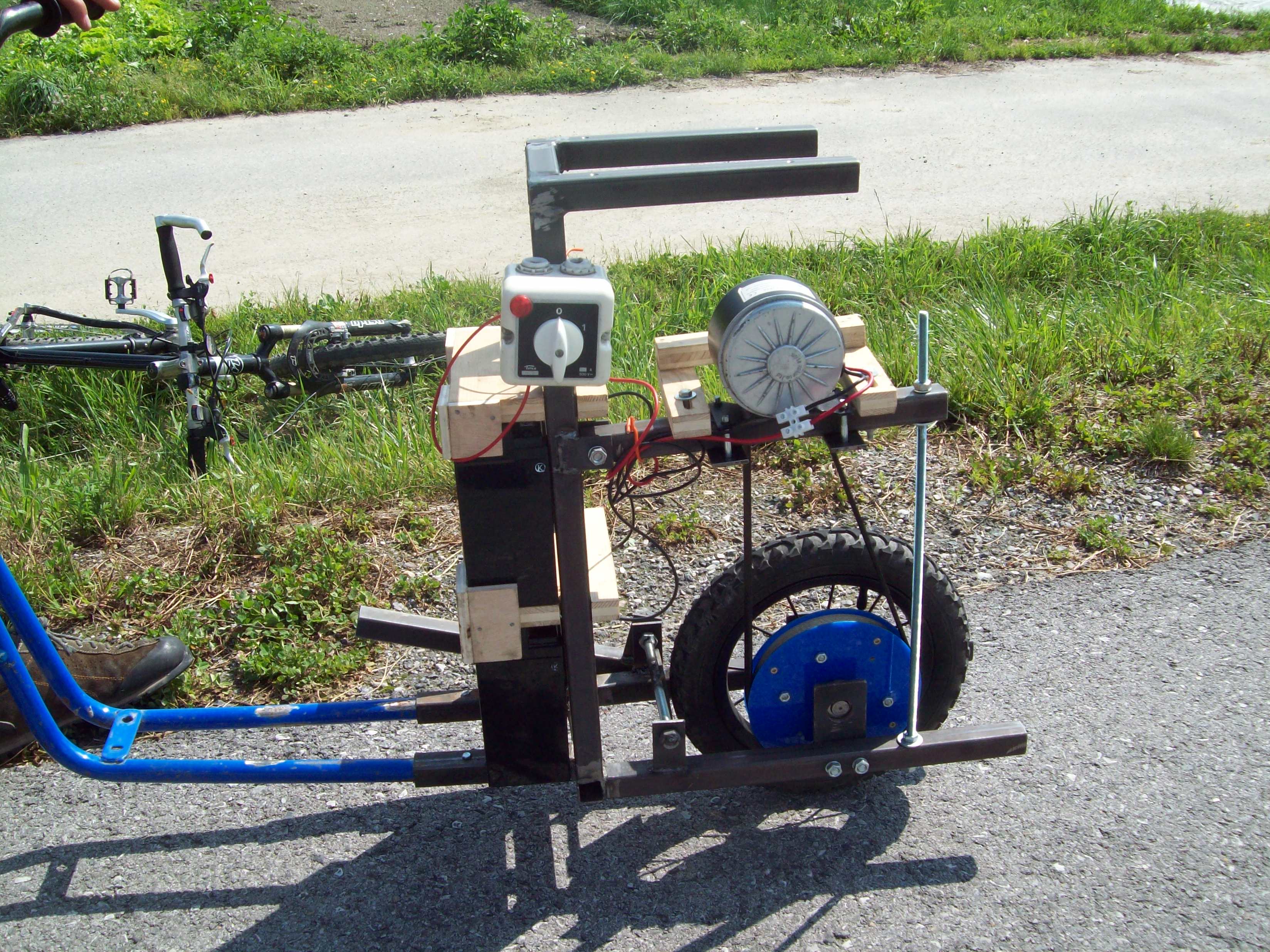
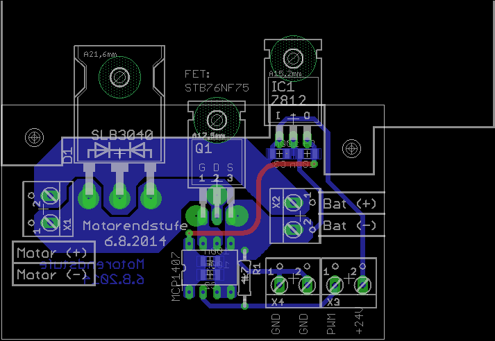
The electronics, however, were surprisingly challenging on this little project. 250W at 24V corresponds to about 13A of DC current (including some losses), so a simple 50A MOSFET driven by a microcontroller will do to pulse-width modulate the motor current and provide continuous power control, I first thought. What I had to find out is that as long as the motor is not turning (the moment you first accelerate), the rush-in current is much higher. It can be about 10 times the nominal current, somebody told me! But switching 130A with a few kilohertz is a totally different story…
The first couple of MOSFETs burned because I was not switching fast enough and during the transition, a huge amount of power was burned, thermally destroying the transistor. Then I bought a superfast gate driver capable of delivering up to 6A to charge and discharge the gate capacitance fast. Too fast in fact, because now I burned a couple of MOSFETs due to overvoltage. When the whole current in the 100A-region changes its path in about 20ns, this creates a huge current spike which excites parasitic tank circuits always present in the wiring and so on. Those resonance effects caused voltages above 300V, too much for the 60V-MOSFET. In the end, some ferrite cores to decrease the quality factor of the parasitic resonances together with a slightly slower edge and a greatly oversized MOSFET did the trick. The layout of the motor driver looks rather simple, but it is very important that the circuitry around the gate of the MOSFET is small because the huge current edges induce spikes everywhere. In fact, they also induced voltages in the PWM line coming from the speed controller at the front, which caused the whole setup to oscillate. Again, shielding, ferrites and lowpass filters had to be utilized to mitigate this undesired behaviour.
Result
With the motor driver working, the rest of this project was rather straight forward cosmetic work. In the end, it turned out quite nicely, although its driving characteristics are not that comfortable. It was quite fun, however, driving around with it (not on public streets, though) because on on a even road without wind, it reaches about 25km/h.