Various electronic projects
Electronics, Projects ·High voltage capacitor bank
Probably every electrical engineering student at some point has the desire to blow stuff up, be it the microcontroller he or she has spent hours on only to find out that the chip itself was broken or whatever. Generally, a good and very dangerous way is to charge a capacitor bank to a high voltage and discharge it through the victim. With 18 capacitors each rated 100uF/300V, all of them charged to maximum results in around 350 Joules. Not a bad bang for a start. Later, I upgraded to 24 capacitors.
Now how to charge them? The easiest source for a couple of kilovolts is probably the transformer and voltage doubler out of an old microwave. Such a device is therefore assembled on a small board. The schematic is quite simple: the original charge pump just as it comes out of the microwave. A second diode is added to the output because we do not want the charge from the capacitor bank to flow back. In the microwave, this is not an issue because the magnetron does not store charge and therefore just operates pulsed.
There is one more catch, however. When connecting the transformer to the empty capacitor bank, the fuse will instantly blow. Some sort of current limitation is needed, obviously. Now one could put a resistor in series with the high voltage supply, but where to get a high voltage resistor from etc. etc. It is much easier to put something in series with the primary side of the microwave transformer, which effectively does the same trick. A good and robust 230V load resistor? You guessed it, an electric kettle with a bit of water in it is just that. As long as it has got some water in it, you really do not need to worry about something overheating here.
 With a piece of a 16mm2 flexible cable on a long PVC stick, one can close the loop and short the capacitor bank, which results in an extremely loud bang and easily vaporizes resistors, small capacitors, ICs, etc.
A WORD OF CAUTION: This is only for educational purposes, do not try this yourself unless you really know what you are doing! It is very important to keep a strict protocol to always switch off, unplug and discharge (!!!) the capacitor bank before you even think about touching it.
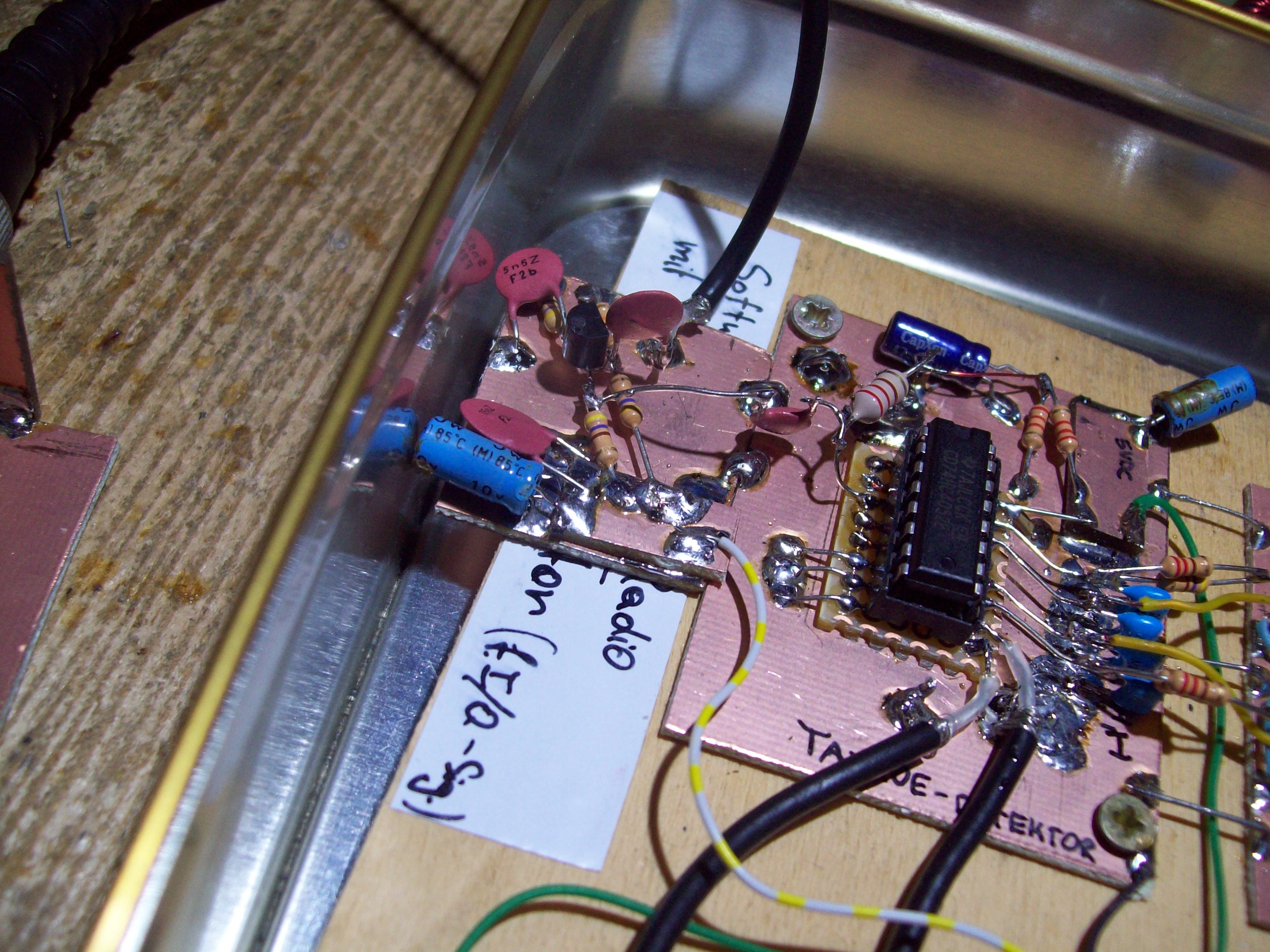
Software defined radio
Having received a HAM license in 2013, I got interested in RF electronics. This little project is the implementation of a simple software defined radio using a direct-mixing approach with an 4-to-1 analog multiplexer, a so-called tayloe detector. The stereo channels of a PC sound card transfer the information to the “digital domain”, where various free SDR-programs can be used to create waterfall diagrams and perform demodulation. The whole hardware is well described in this article. The individual modules are the tayloe-detector itself (bottom left PCB), the lowpass filter and amplifier (top left PCB), the clock generator (bottom right PCB) and the powersupply (top right).
 An additional input amplifier was added later, which did improve the SNR, but also caused intermodulation products from very strong stations due to its non-linearity combined with the lack of input filtering. For this reason, amplification before the mixer was subsequently avoided again.
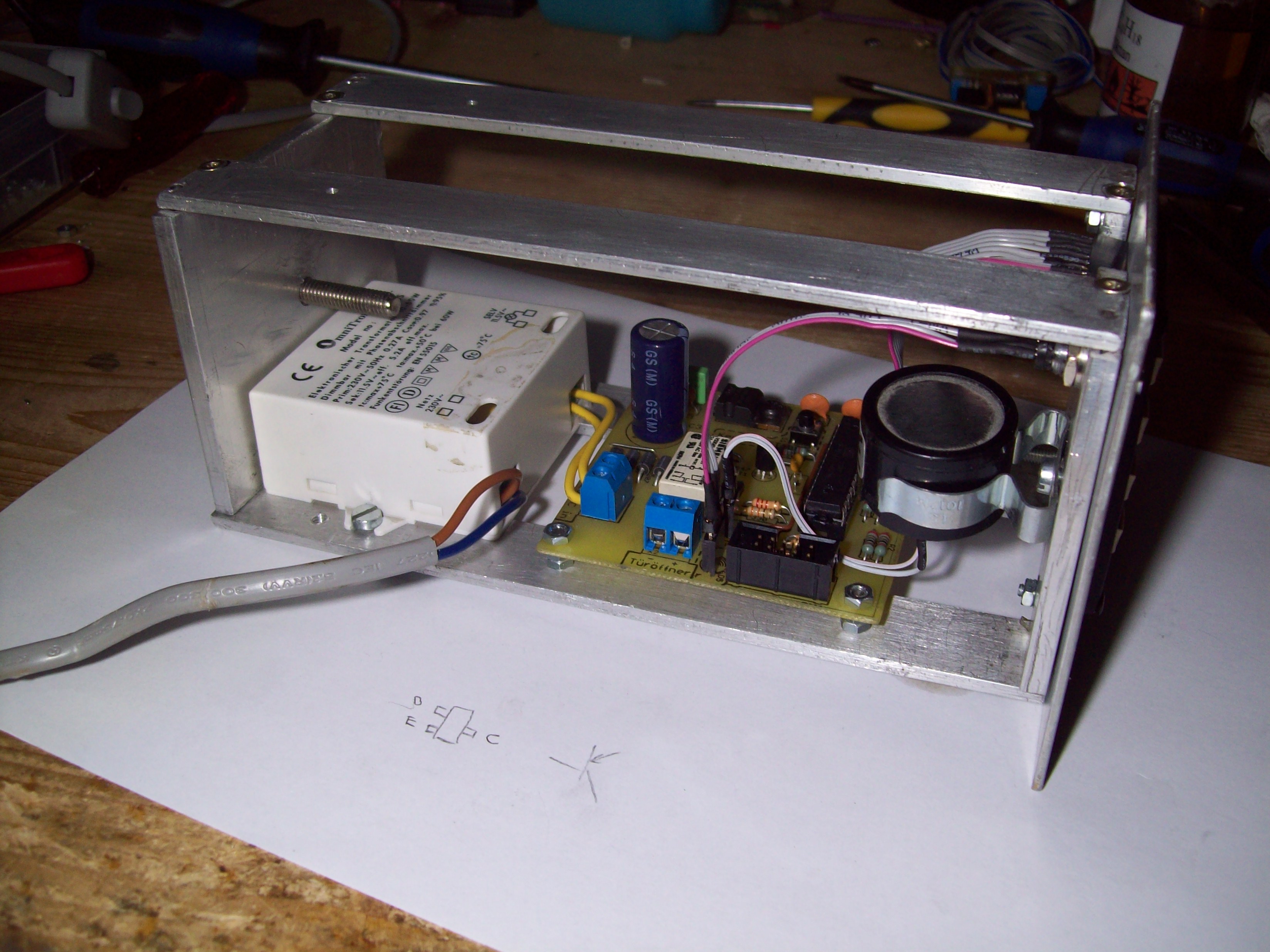
Electronic combination lock
An already existing combination lock was overhauled completely and fitted with new electronics, only the aluminium frame and the keypad were reused. The lock was originally built by students for a room (inside a building, not accessible from the street) so that only certain people could enter. After some time, however, it became unreliable and would behave strangely. The new hardware was build more tidy and rugged than the old one, on a home-etched PCB with an ATmega48. A friend of mine wrote the software for it.
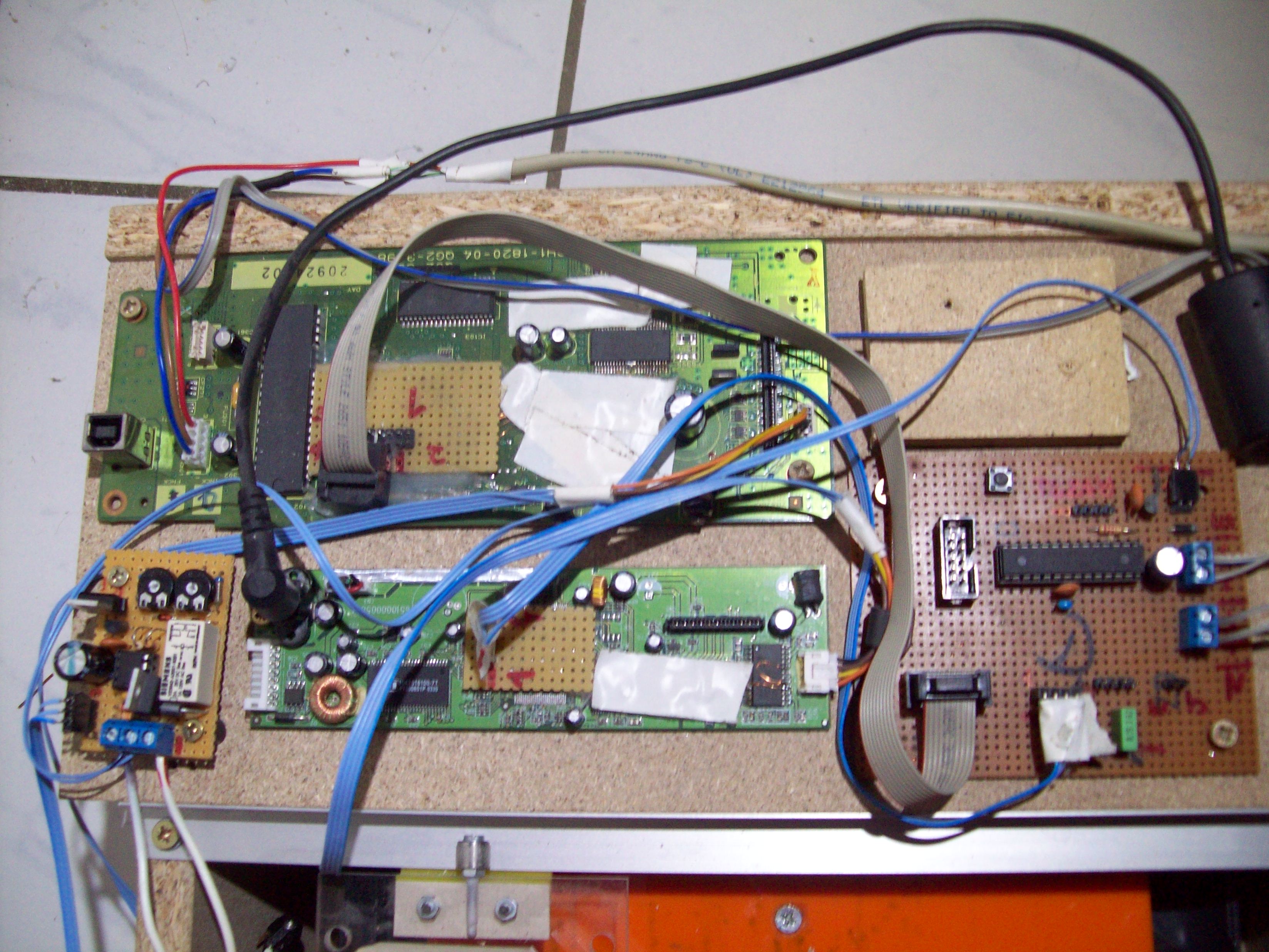
Pen Plotter experiment
This is a “what-can-I-build-with-things-lying-around”-kind of project. I had an old printer and flat bed scanner that I would not have used for anything else, so I thought, the scanner is able to sweep the long edge of an A4 sheet, the inkjet printer is able to sweep the short side, so why not combine those two and have a kind of plotter. I ripped the workings out of both devices, assembled them on a wooden frame and extended the scanners head with a sheet of plexiglass.
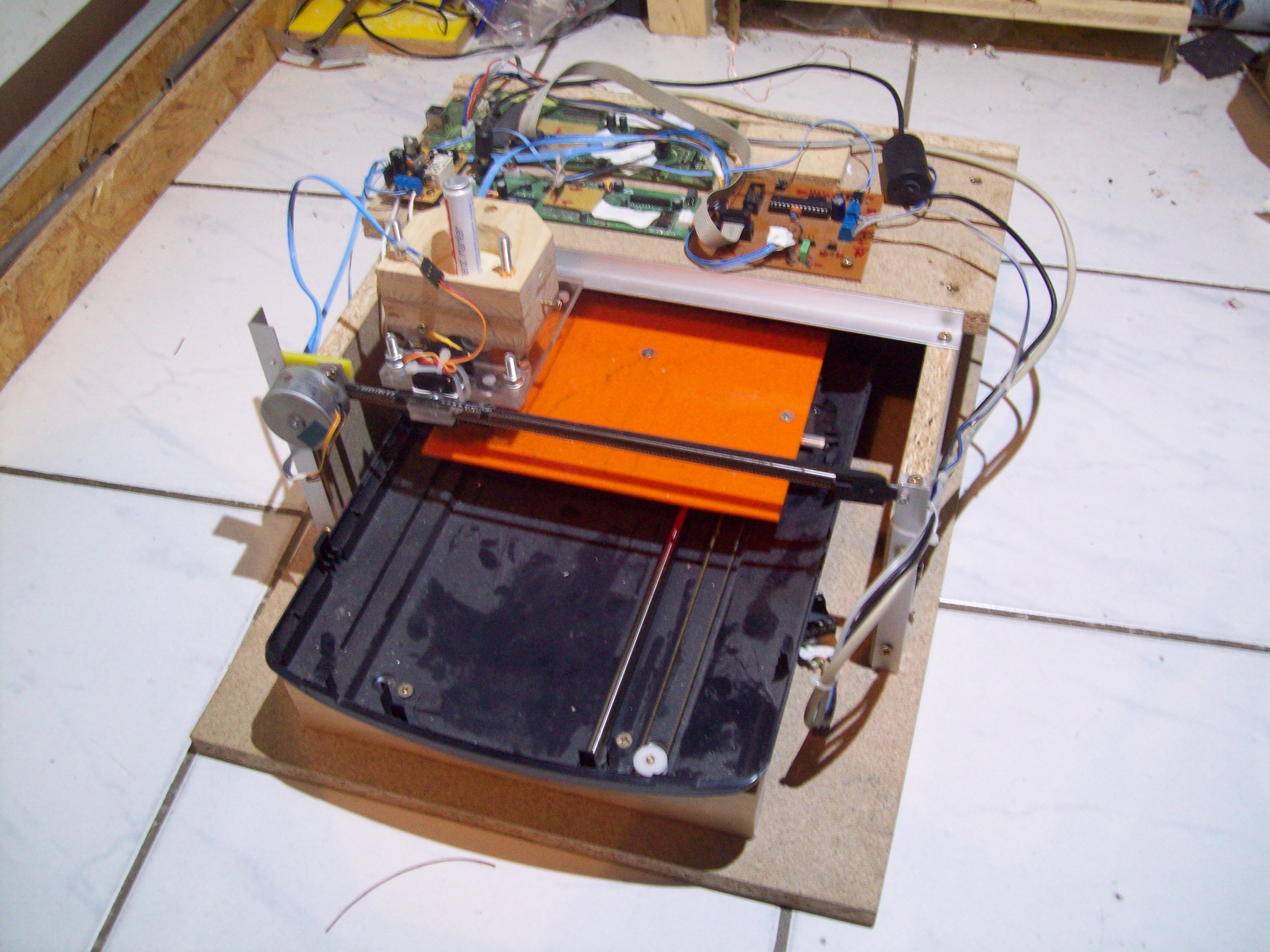 First, I intended to build dedicated drivers for the motors, but then I thought: Why this work when somebody has already done all of this for us? So I used the original power supplies and drivers of the printer and scanner. The only thing I had to do is to cut the input tracks to the stepper driver ICs and connect them to a small microcontroller. Couldn’t be simpler.
 Originally, an idea was to drill home-etched PCBs with it, but I quickly realized that the scanner’s linear guides are just not strong enough for that. So I just attached a pen and it became a simple plotter. Honestly, this device can do nothing that a normal printer couldn’t do, but it is so cool to watch a machine draw something with a pen.
HAM radio antenna for 2m band
After receiving my HAM license, I of course wanted to establish far contacts from a mountain top or so, and for that, a directive antenna helps. There are many instructions online on how to build a Yagi antenna for the 2m band, with the right dimensions for all the elements and so on. With the help of my small lathe, I built one where the elements can be unscrewed so that it can easily be tied to a backpack.
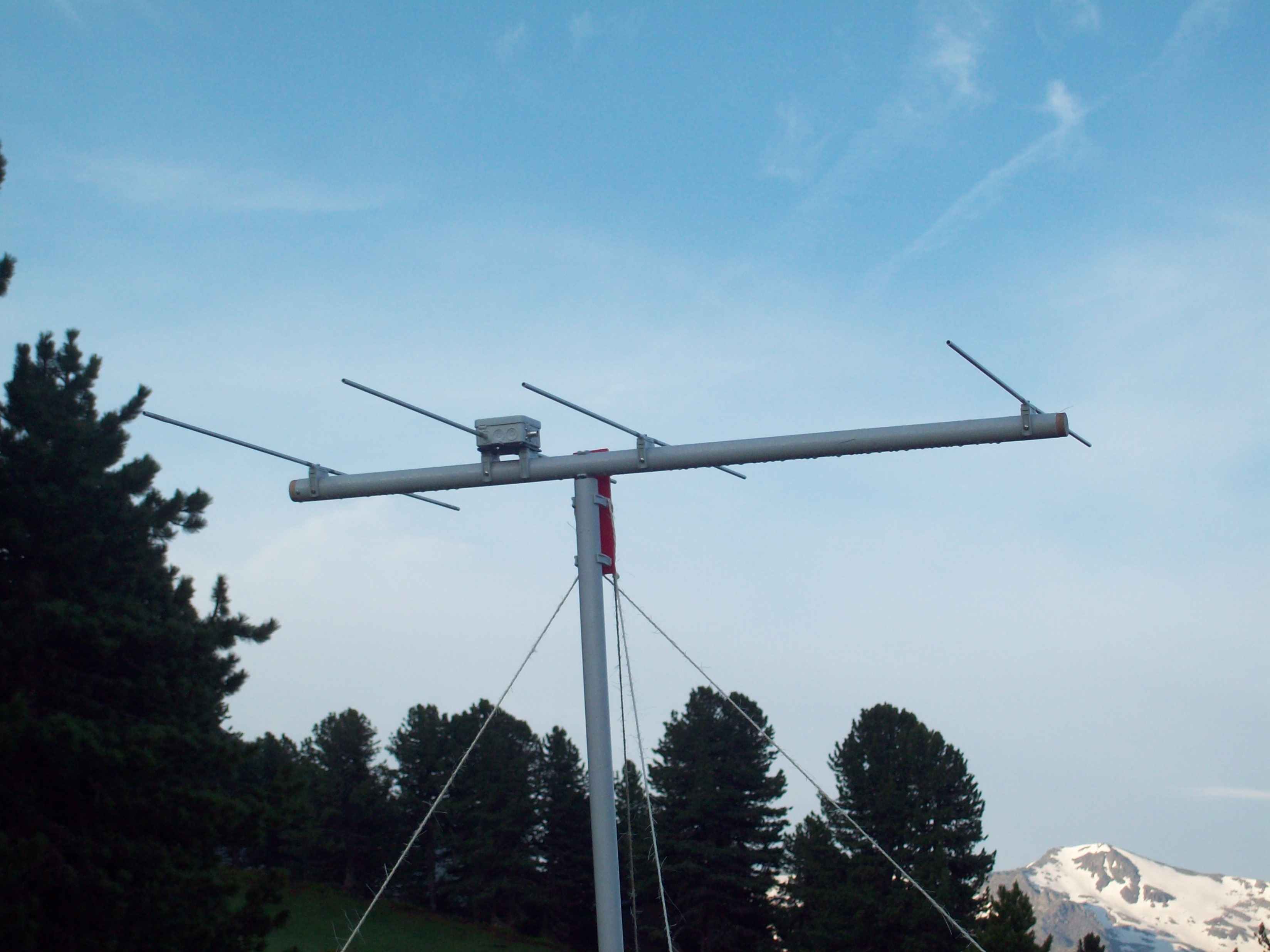
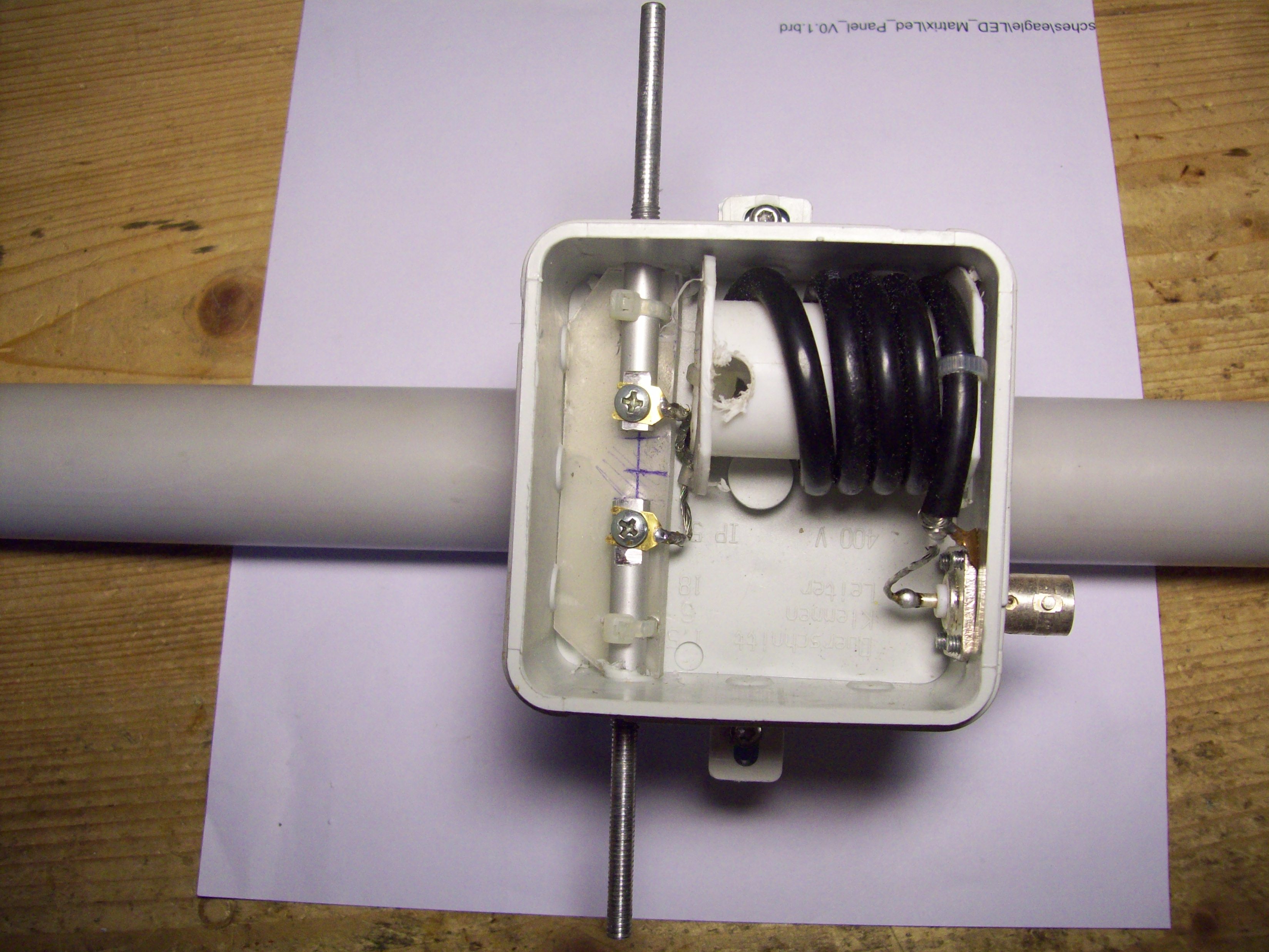
 The active dipole is fed directly from the unsymmetric coax line for simplicity. To avoid currents on the shield of the coax, a choke is formed by running the coax around a spool a few times.
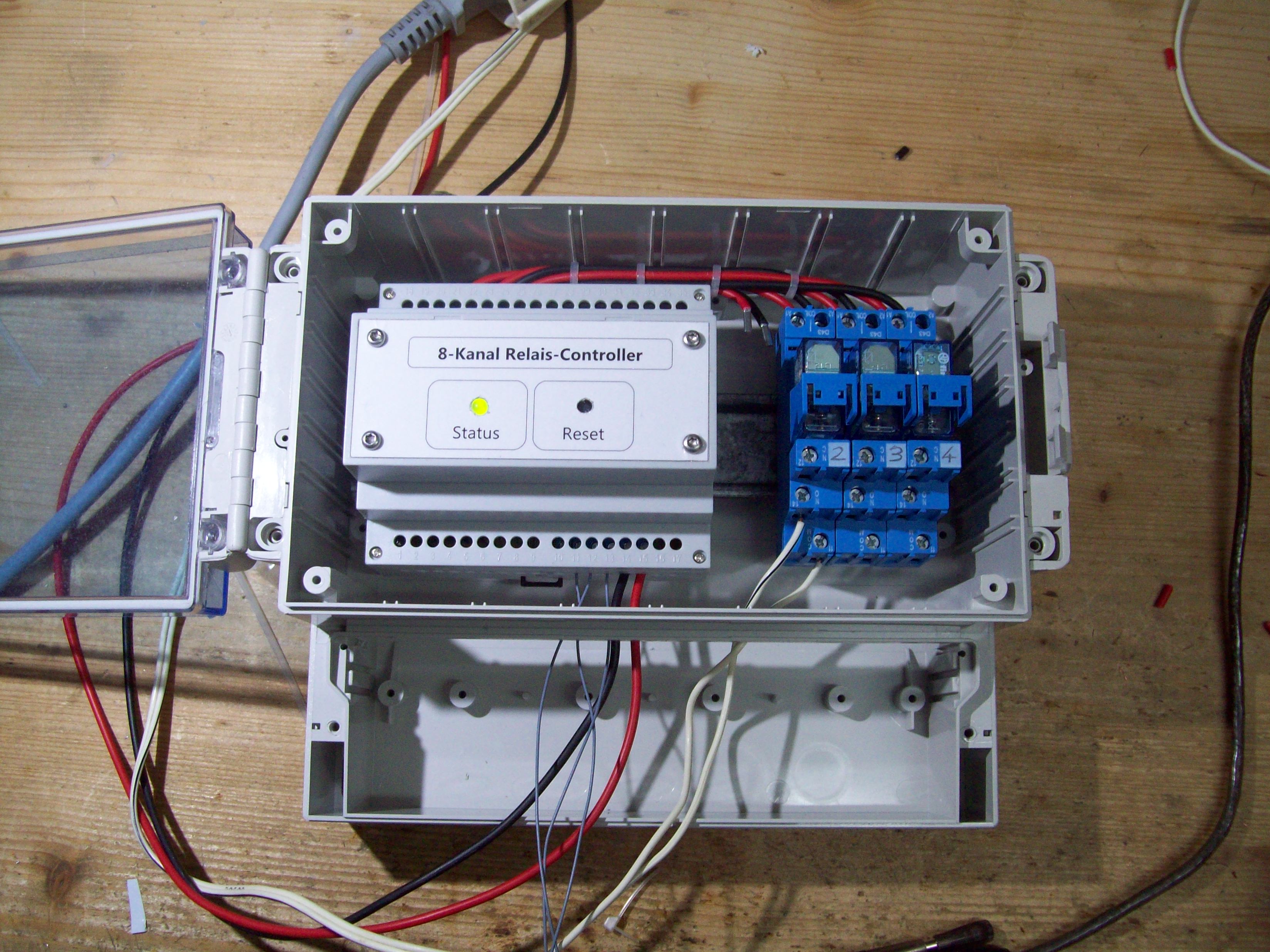
Relaycontroller for DIN-rail
This project was paid work for somebody. It replaces a small and overpriced device with only four relay channels. It has the same interface via text-based commands over RS232, but in a standard form factor that can be mounted on a DIN-rail. Up to eight relays can be mounted beside and chosen to fit the task. Simon did the software again. We sold it (privately, though) quite a bit cheaper than the original controller and it still felt like a lot of money for us.
Roboter Rufus
RUFUS is one of my first (bigger) electronics projects. This robot with tracks is meant to operate a bit like a forklift. The mechanics were welded with the help of my neighbor in his workshop. It was also the first project for which microcontrollers were used. You can control the robot from a PC-tool written in Visual Basic and transfer the commands via a Bluetooth module to the “Master AVR”, which passes the information over the robot’s internal I2C-bus to different submodules.
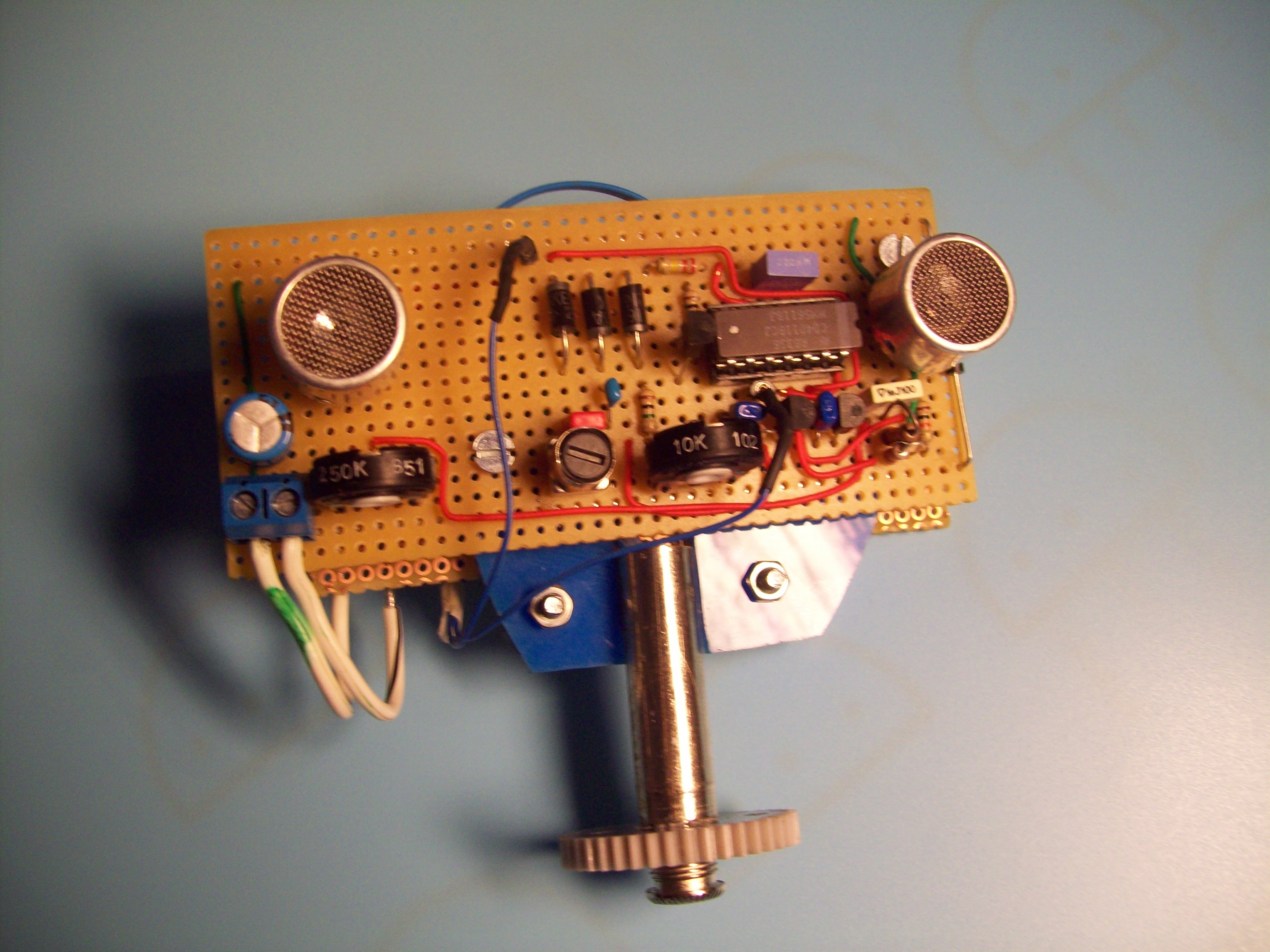
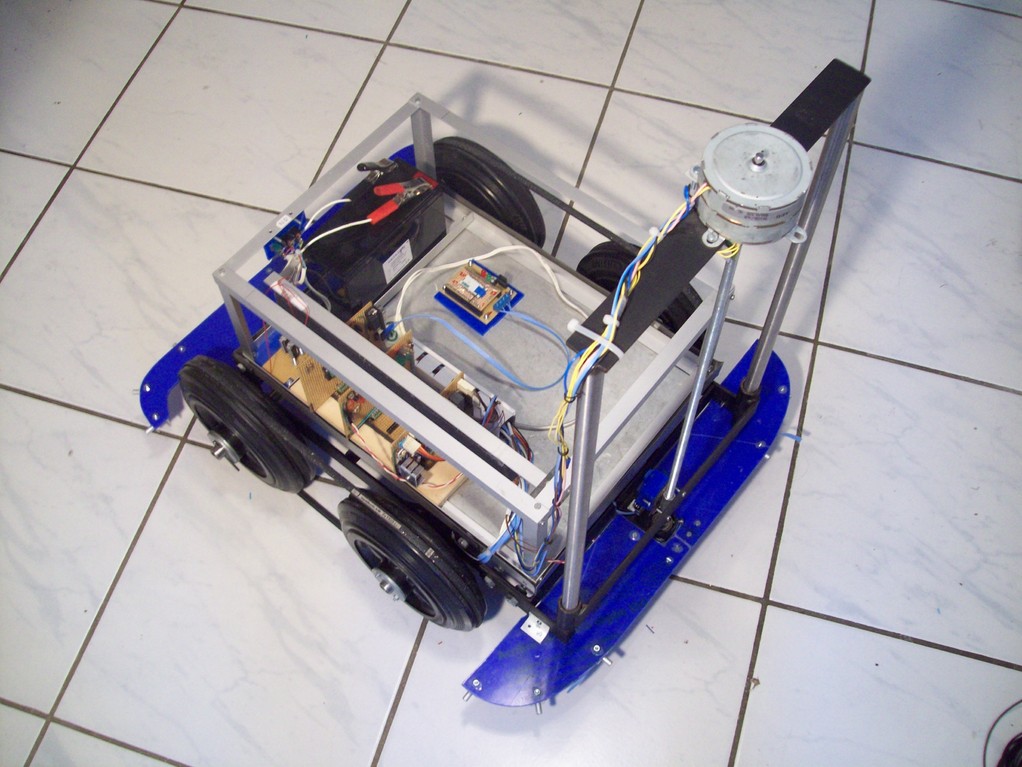 One interesting device on this robot is its ultrasonic distance sensor. It is based on this article and was refined by the help of various people. In the end, it was capable to detect objects up to 2m or so with a resolution of a few centimeters. The idea was to rotate the sensor like a radar and map the surrounding terrain.
 In the end, this huge project was obviously never really finished. However, I learned many useful things along the way.