Matrix Blue
Electronics, Projects ·Introduction
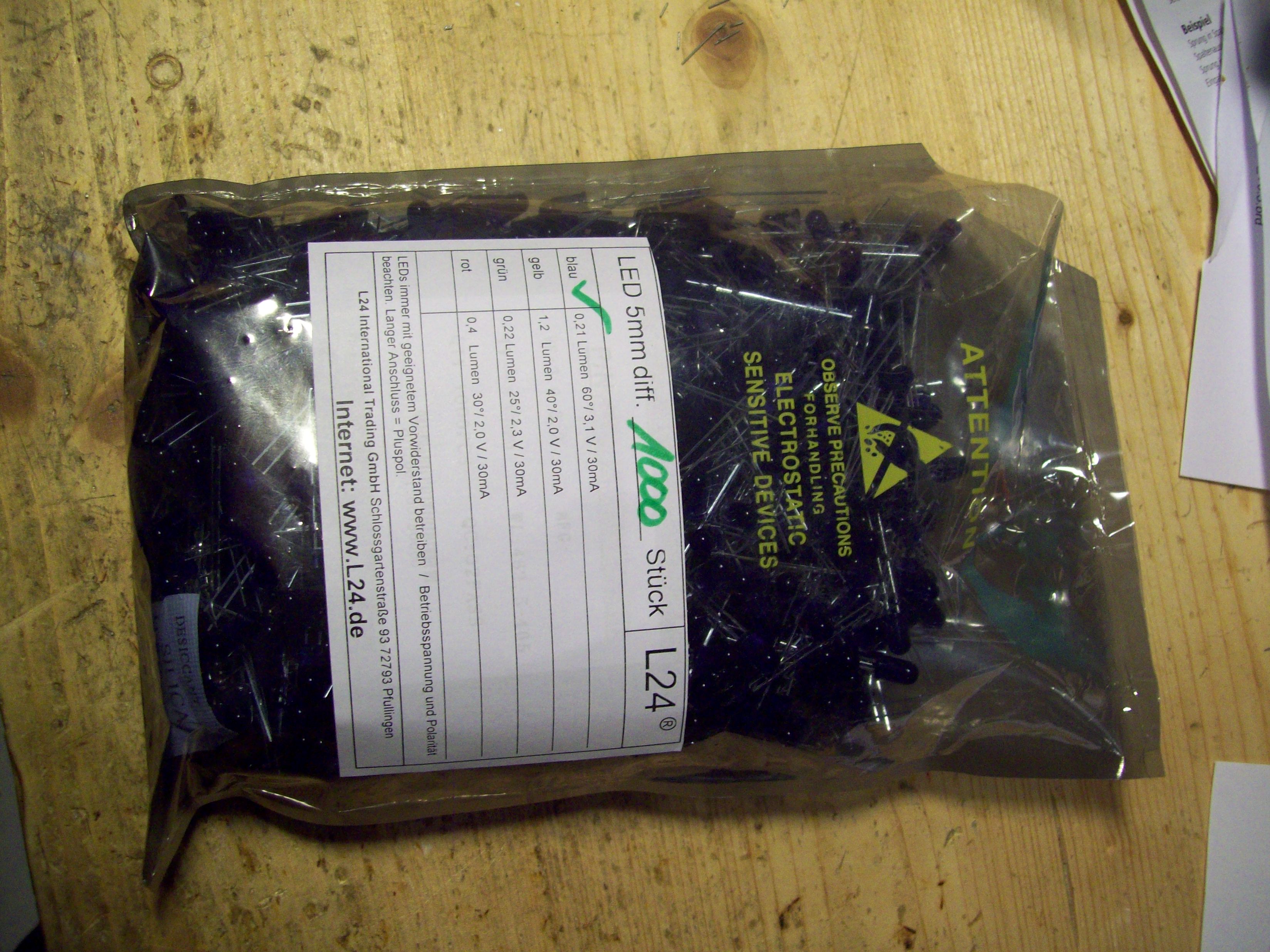
I guess in the career of any electrical engineer, he or she will come to the point of building some sort of LED display. The basic principle couldn’t be simpler - just switch on and off individual LEDs arranged in a grid to display text or small animations. In detail, of course, there is always more to it than one might initially think, but anyways, this is my and my friend’s take on such a project. It is composed of standard 5mm leds from Ebay, although of blue color for the cool look.
The build
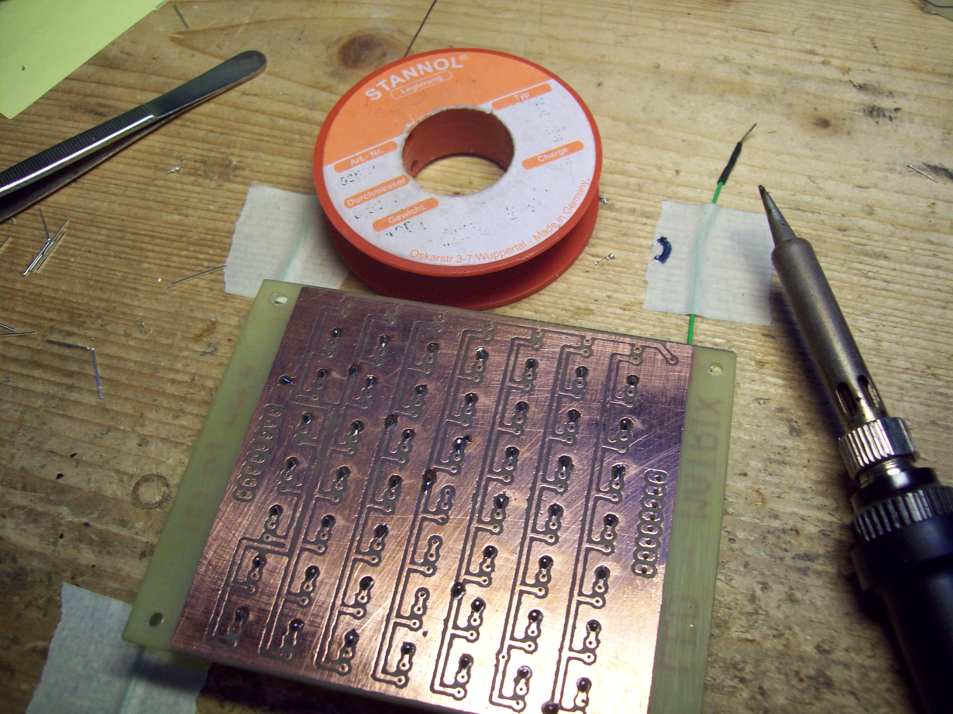
The display is constructed from individual PCBs carrying 7x8 LEDs in a matrix configuration, with the anodes connected in rows and cathodes in columns. All the PCBs are etched, drilled and soldered by hand. To coat the front of the PCBs, ordinary black spray paint is applied before soldering the LEDs.
 On the back of each module, a small driver PCB is attached via pinheaders. This board contains the row driver, a standard 8-bit high-side driver in a DIL package. As there are only 7 rows in the complete matrix, the row lines are directly fed from the microcontroller to each row driver via a flat ribbon cable. For the columns, each element has a 8-bit shift register/latch with low-side driver in one package. They all sit on a 8-bit data bus and are addressed in binary via three address lines from the MCU.
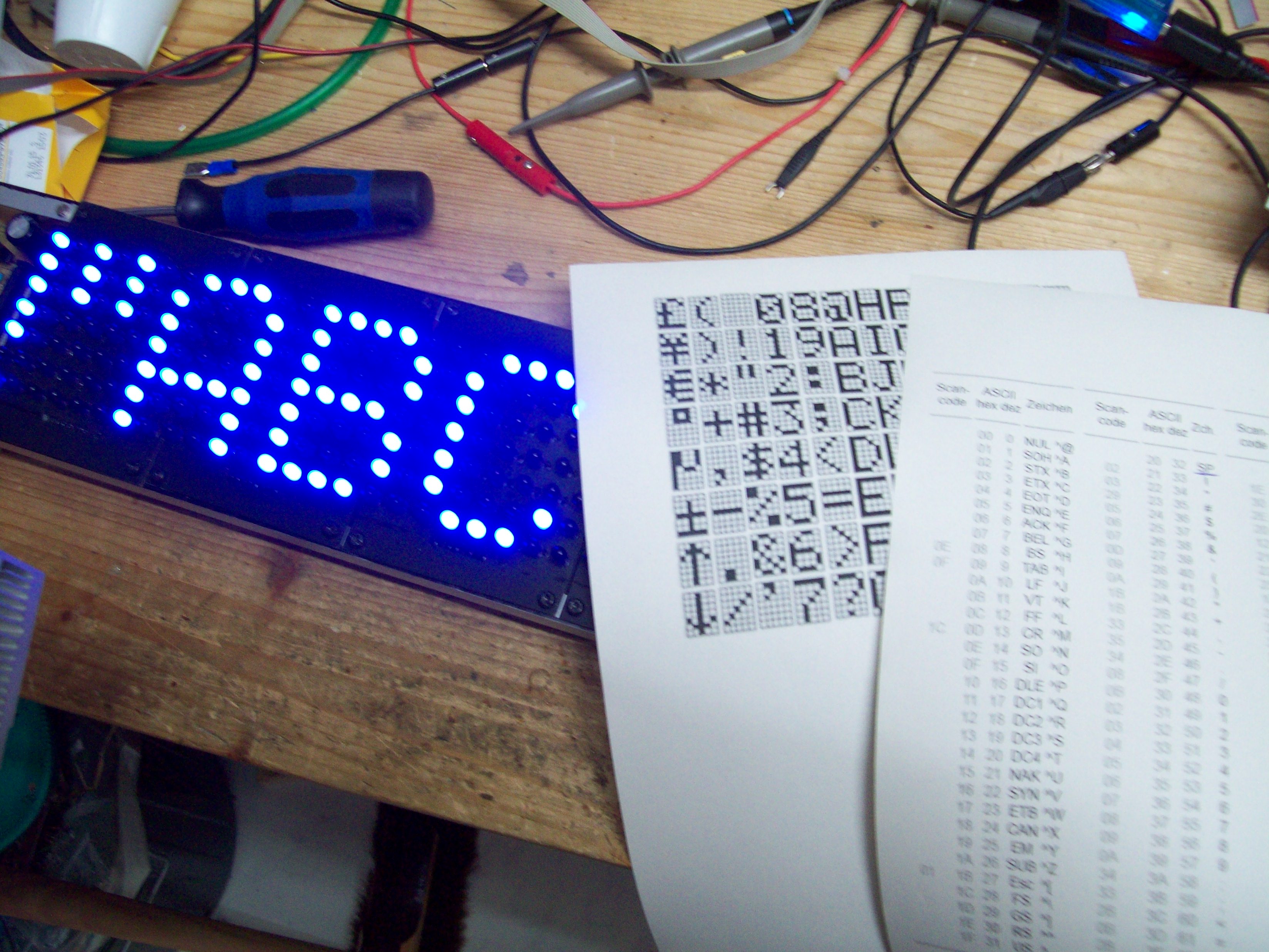
When displaying an image, the microcontroller first sets up all the column latches with the pixel information for the first line. Then, it turns on the first row by enabling the first bit of the row drivers. It lets the LEDs emit light for a couple of milliseconds, then turns off the row driver again, subsequently shifts out all bits for the second line, enables the second bit of the row driver, and so on. A classic multiplexing process, so to say.
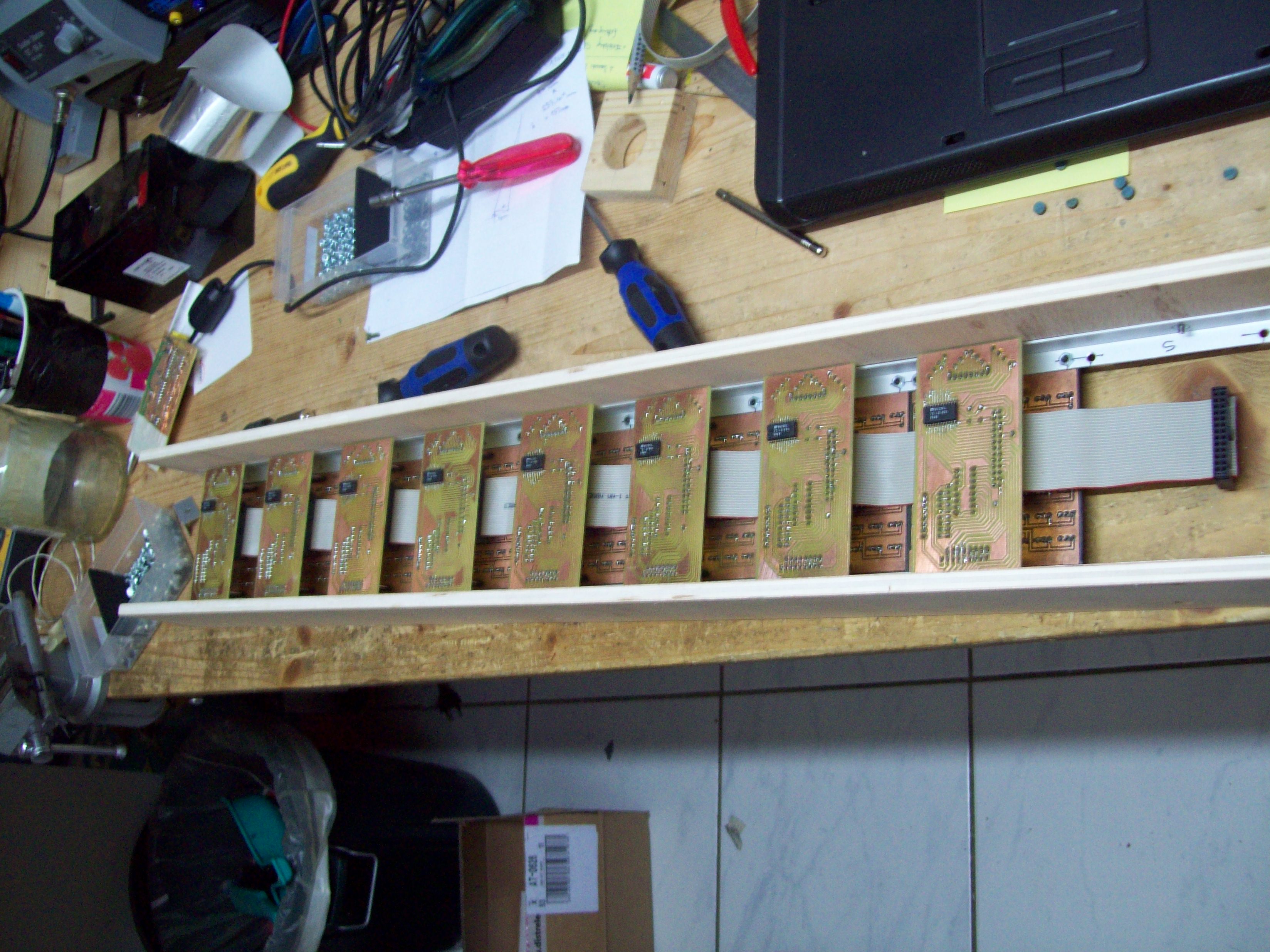
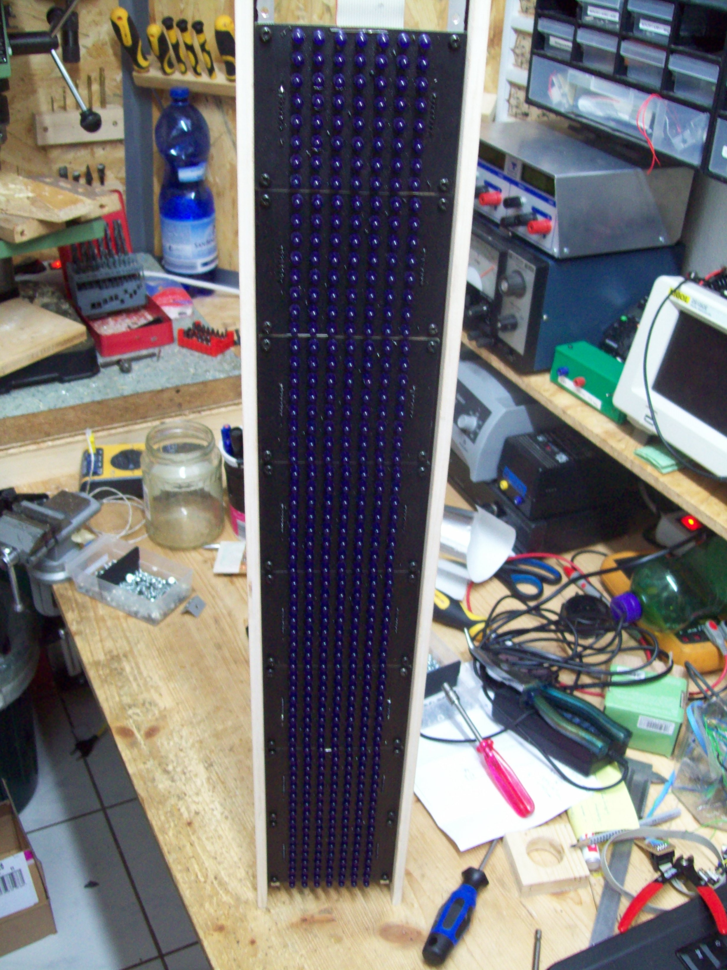
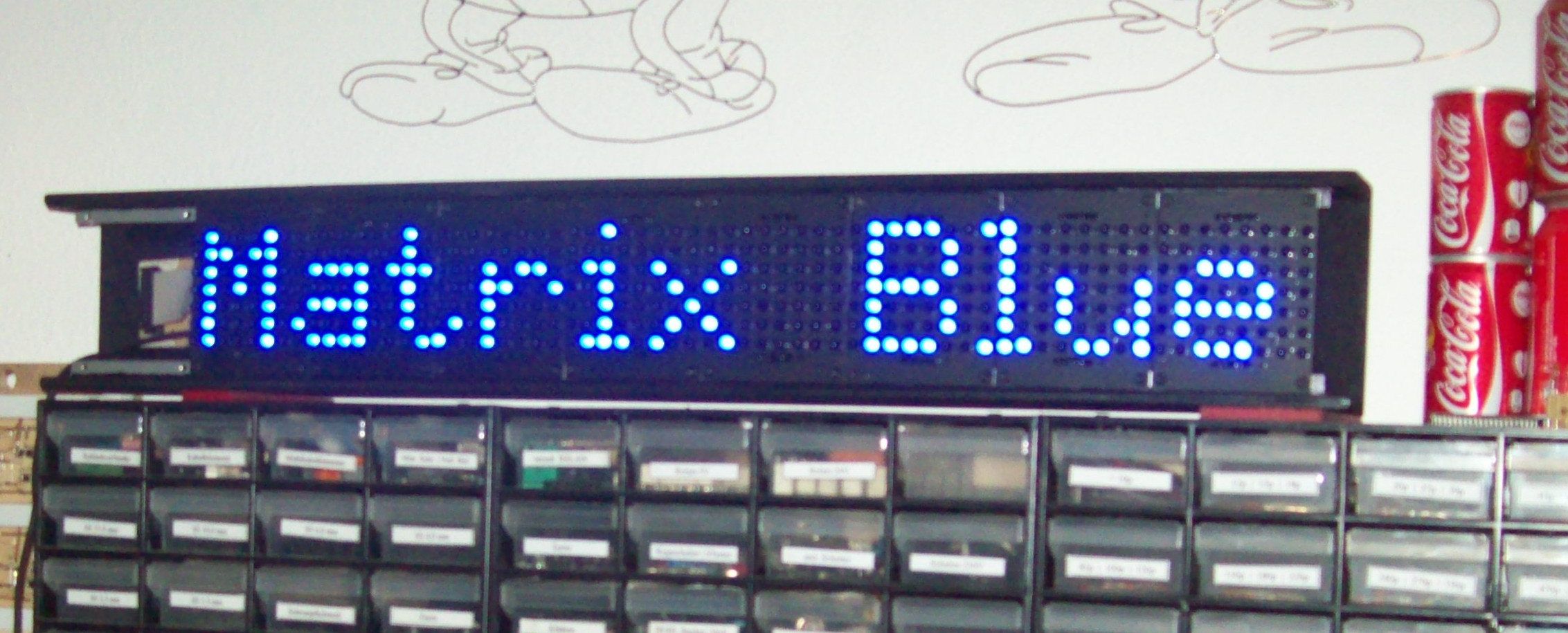
When everything is assembled, it already looks quite impressive.
But it is of course the software that does the magic and brings the individual lights to life. In this case, the software is written in C and listens on the serial port for characters and commands to display.
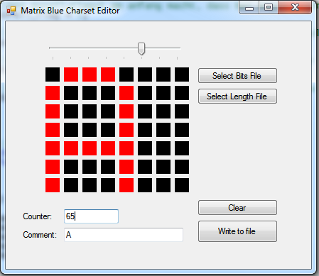
Setting custom characters
To program the individual characters, a small helper tool is written in Visual Basic (that’s what I used at that time for PC software). It allows to visually design a character set and automatically save the binary information in an array in C syntax that can then be compiled in the firmware code.
Results
In the end, me and my friend build two of those matrices that could be mounted side by side and scroll the text synchronized. The resulting display had a remarkable width of about 1.3 meters!