Masters's thesis
Electronics, Projects ·Abstract
This thesis is concerned with systematically describing noise in switched capacitor (SC) circuits. In the first part, simulation methods such as PSS/PNOISE, transient noise and regular noise analysis are employed as well as an analytical approach considering the underlying continuous- and discrete-time signal processing mechanisms. Additionally, the PySCAN simulator is developed to be a universally applicable tool for noise investigation of SC circuits. It is used as an alternative to the simulation approach, allows to modify all circuit parameters and obtain results quickly. PySCAN takes a netlist and a configuration file with phase definitions and switch settings as input and computes a noise summary. All those methods are evaluated and discussed utilizing a simple SC integrator as a test vehicle. In the second part of this thesis, the methods are applied to an optical sensor interface containing a photodiode and a SC signal processing frontend with the aim to improve the SNR. Data from PSS/PNOISE simulation and a representation of the non-stationary processes caused by noise current integration are combined in a simulation-based noise model. Based on the PySCAN simulator results, a number of design changes are evaluated regarding their improvement potential. Among those, the reduction of the photodiode capacitance and the improvement of the first operational amplifier have the largest effect.
A comment
My master’s thesis was a cooperation project with ams-OSRAM AG, which I successfully defended in June 2022. The initial idea was to analyze the noise response of an existing optical sensor front-end circuit based on the switched capacitor (SC) principle. This involved identifying the dominant noise mechanisms, establishing a simplified “engineering model”, and proposing suggestions for future optimization. Not far into the project, I got excited about the different methods to assess noise in general SC circuits. As a consequence, the thesis evolved a bit into a study of different numerical methods such as the commercial transient noise and PSS/PNOISE simulation as well as implementing my own simulation tool based on an algorithm inspired by [1].
Noise in switched capacitor circuits - a quick overview
The noise response of a SC circuit is a bit more tricky to compute than e.g. of a simple amplifier. While the latter can usually be described quite well as a Linear Time-Invariant (LTI) system, SC circuits are sampled systems and have to be modeled as Linear Time-Variant (LTV) systems to accurately predict their noise response. SC circuits usually operate in a number of phases, between which switches are flipped to change the connections. The time-variant nature causes frequency-translation behavior, often referred to as “noise folding”. The same effect is commonly known as aliasing in case of an ADC, where the input sampling action folds down signals and noise from frequencies above fs/2 into the signal band. A Sample-and-Hold circuit is also typically a SC circuit, after all.
Noise in LTI systems is usually calculated by identifying all (relevant) noise sources, calculating the transfer functions from all sources to the output, and adding up the individual contributors (power spectral densities) there. This is how one would do it in a hand calculation, but is also the principle how noise simulation in e.g. a SPICE simulator works. However, this method relies on the system being linearized around a DC operating point at one time moment, and does not work when the circuit topology is constantly changing.
One intuitive and powerful method to simulate noise in basically any circuit is transient noise. It is fundamentally just a transient simulation, but for every noisy component such as a resistor, a noise source fed with suitable pseudo-random numbers is inserted in the circuit. Basically any circuit can be simulated, but it is quite computationally intensive to get results with even moderate accuracy. Another approach are Periodic Steady State (PSS) methods, which are offered by some modern circuit simulators. They internally rely on LTPV system theory, meaning that the system behavior can vary over a time, but must do that periodically. SC circuits usually fall into this category as well, making PSS and the associated noise analysis (PNOISE) a very useful tool. However, despite being a small-signal method, also PSS/PNOISE can be quite computationally expensive even for circuits of moderate complexity.
One observation about PSS simulation is that it allows the system dynamics to vary continuously over time, which makes it applicable to a large class of systems, including mixers driven with sinusoid signals for example. However, SC circuits usually do not vary continuously, but only in discrete time moments - namely the phase transitions when the switches are flipped. Between those time points, they still behave as LTI systems. To exploit this observation, [1] introduces a mixed time-domain/frequency domain method especially suited for SC circuits.
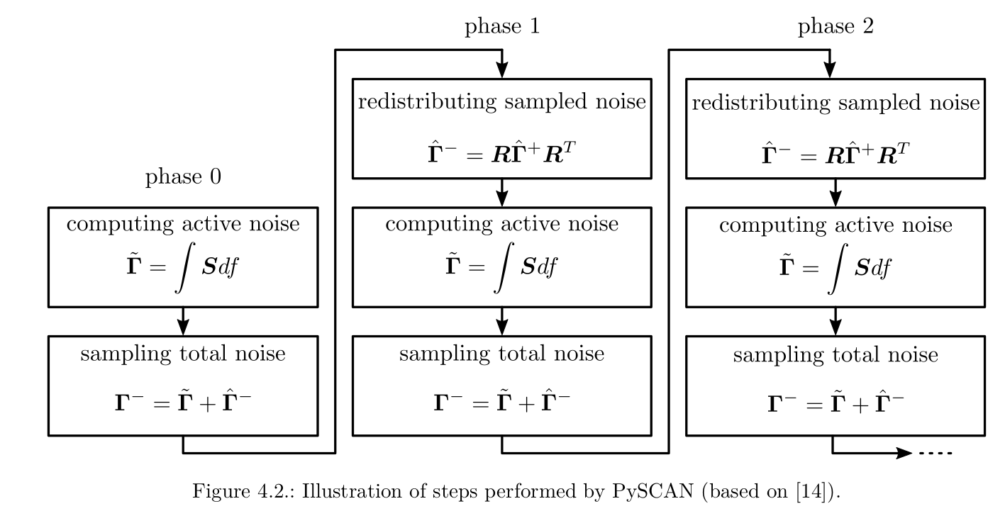
The method proposes to compute the noise on all capacitors of circuit between two switching time points using the traditional frequency domain approach of multiplying source noise densities with (squared) transfer functions and adding up all contributors. To cover the sampling action, it assumes that the noise voltages on all capacitors are sampled at each phase transition (switching time point). By design, SC circuits will have some memory of previous phases, otherwise there would be no need to perform all but the last phase of course. So some noise charge will make it to the output, and it is exactly this noise charge that we would be missing if we just ran regular noise analysis in the phase where the output is ready.
To include these sampled noise charges from previous phases, the authors of [1] propose to use transient simulation to model the large-signal behavior of the circuit. So we have a transient simulation that models how the charges flow from capacitor to capacitor during the phases (sampled noise), and in each phase we inject the noise caused by the sources in that phase on top of that (active noise).
 Mathematical steps performed in PySCAN
This is the basic operational principle of PySCAN, my implementation of the procedure from [1]. However, I extended the small-signal noise computations to include correlation between different capacitors. Neglecting correlation is usually not a bit source of error in such circuits, but it can become apparent if you have one dominant noise source affecting multiple capacitors, for example when you have a switchable capacitor bank. The large-signal transient simulation is implemented by successively placing an initial condition of 1V on each capacitor and running a simple transient simulation, after which the state of all capacitors is recorded. This information is compiled in what I called the redistribution matrix R - a matrix describing how sampled noise charges propagate in the circuit when transitioning from one phase to the next.
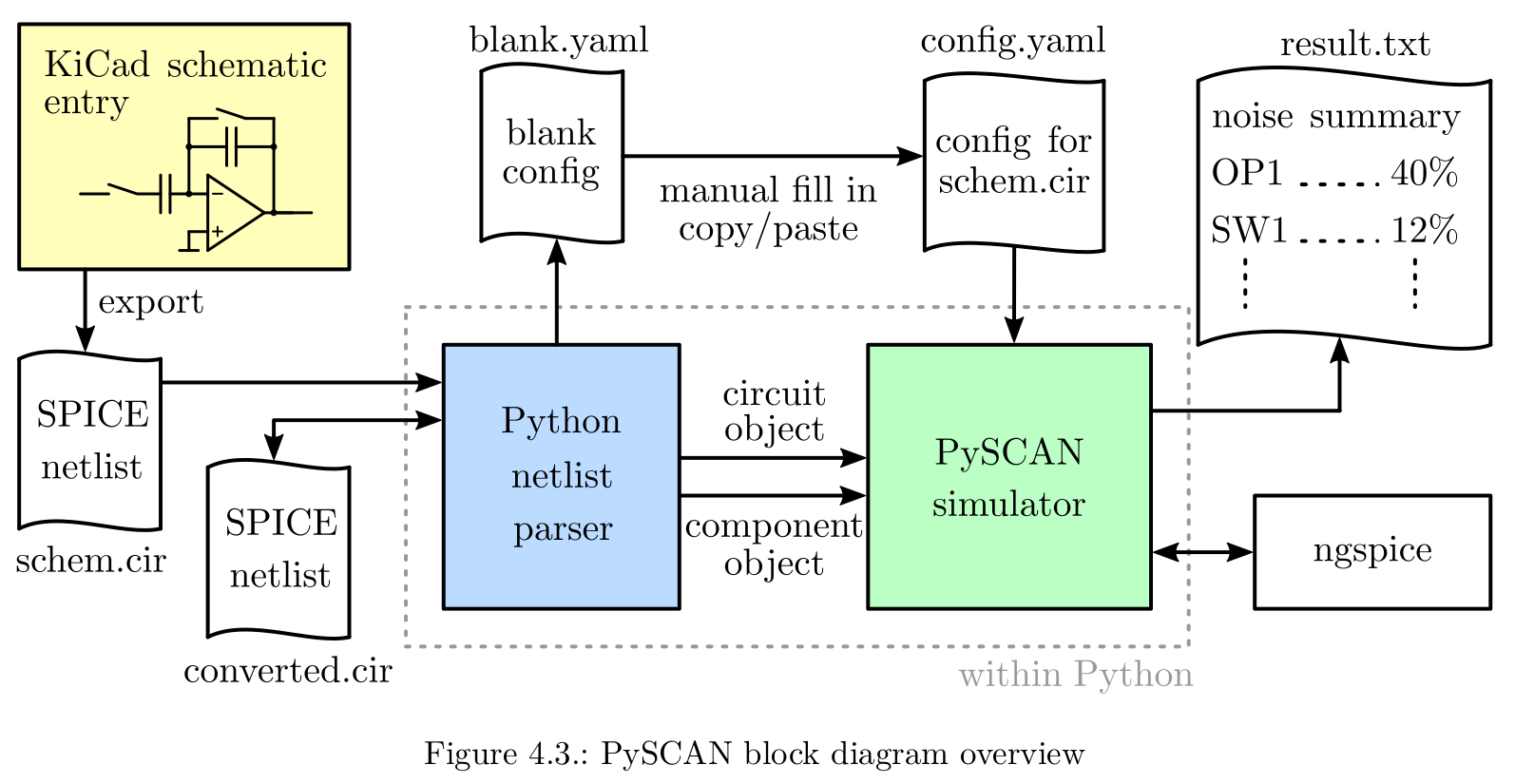
The tool is implemented in Python, relying on the PySPICE package to be able to perform the aforementioned simulations on a circuit netlist. The data is gathered in numpy matrices, where the iterative process of accumulating noise is carried out.
 Block diagram of PySCAN software.
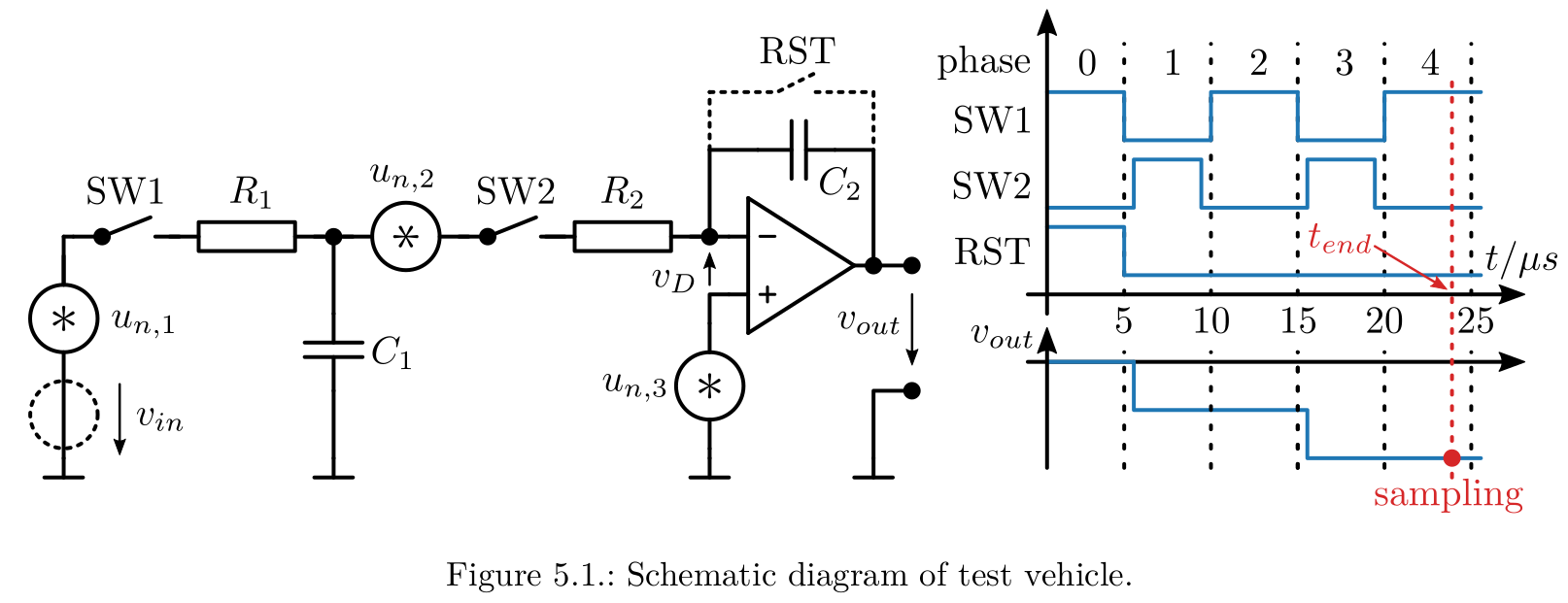
All this theory sounds very fancy, but does it actually work? To demonstrate, a simple SC integrator is used as a test vehicle. It performs two accumulation cycles of its input voltage, which is just 0V in this case, to see the noise at the output after those phases.
 SC-integrator used as test vehicle for the methods
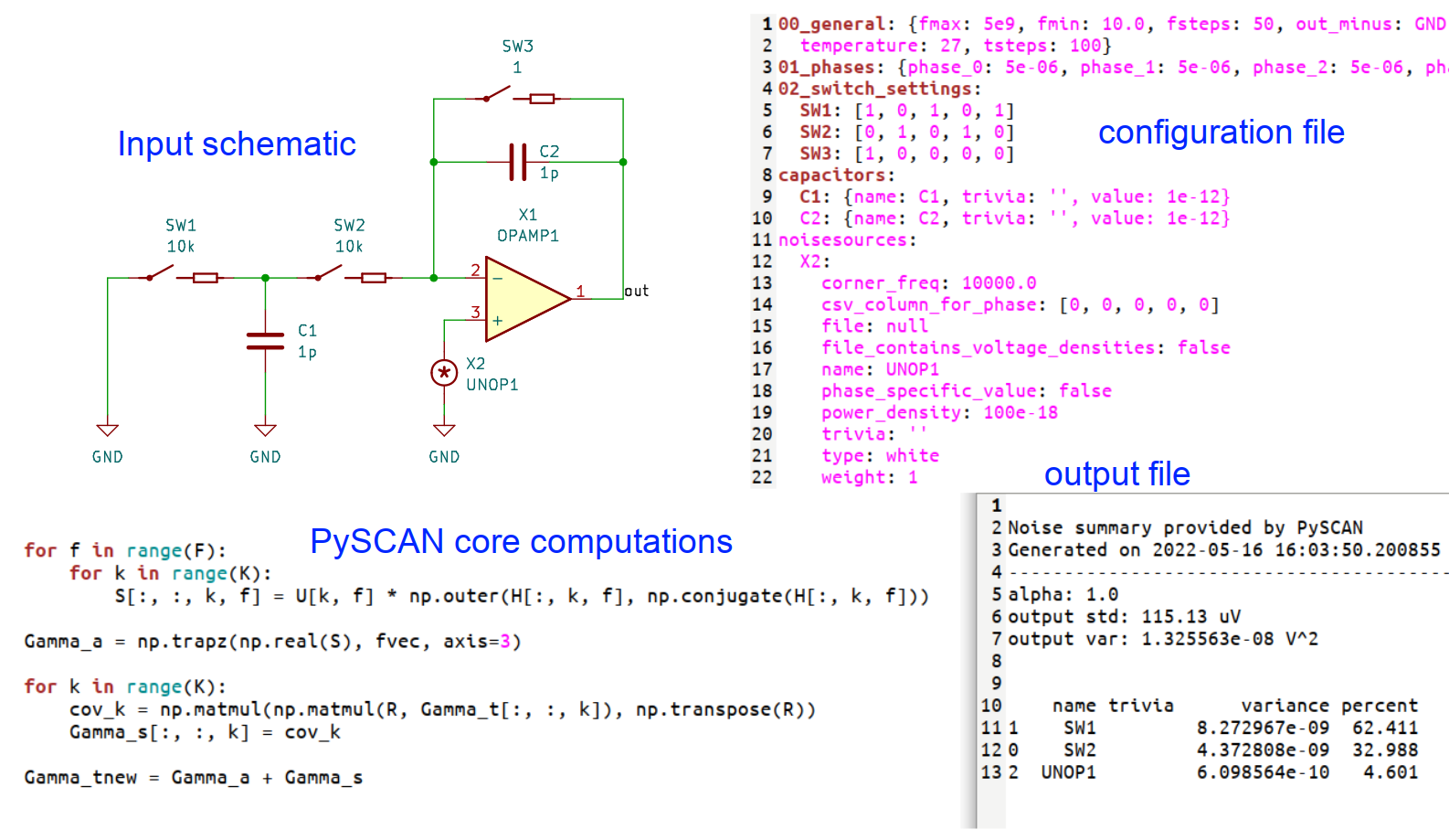
The following figure illustrates the workflow. The circuit netlist can be entered in KiCAD, and additional information about the number and duration of phases plus the settings of the switches in each phase is given via an separate configuration file in yaml syntax.
 Application of PySCAN to an SC-integrator
The output noise power (variance) of different methods is compared relative to the closed-form analytical solution, which can still be calculated for this relatively simple circuit by hand. Both PSS (with PNOISE) and PySCAN are able to predict the output noise power with a few percent difference from the analytical solution. ACN denotes basically a stripped-down version of the PySCAN principle using regular noise analysis and coefficients derived from knowledge of the circuit (capacitor ratios etc.). TN (transient noise) is less accurate, especially if the maximum frequency of the noise sources is not high enough.
 Comparison of different methods applied to the test vehicle for 1GHz and 5GHz simulated bandwidth. Alpha denotes the ratio C1/C2.
Conclusion
Generally, one can simulate the noise response of SC circuits very well with PSS/PNOISE. PySCAN works with a subset of LTPV systems that change their dynamics only in a finite number of discrete time points (phase transitions). Functionally it is fully covered by PSS/PNOISE, but it can be orders of magnitude faster with comparable accuracy if its underlying assumptions are met. I do not think this method will revolutionize the circuit simulator business, but it can be a handy tool to sweep various parameters of a system and get an estimate for the impact on its noise response within seconds. This is also what it was created for in this project.
Apart from all of this, I got quite excited about “bringing a bit of mathematics to life”. I mean you can always write down all sorts of fancy-looking equations, but to see such an abstract, matrix-based method producing results that agree so closely with a completely different method used in commercial simulators is really cool I think. If you are interested in this, you can always drop me an email.
[1] G. Varga, A. Süss and B. J. Hosticka, “A sequential method for noise estimation in switched-capacitor systems using a switching time-frequency domain,” 2011 20th European Conference on Circuit Theory and Design (ECCTD), Linköping, Sweden, 2011, pp. 500-503, doi: 10.1109/ECCTD.2011.6043398. IEEE link